Track A (No-Kit Preservation Clean) Active: Preserves the bowl-to-intake gasket (28) and bowl-to-throttle gasket (54), removes only threaded brass jets (34, 37, 39, 40, 51) and filter element (17), and keeps factory-staked check valves (30, 38) and butterfly screws (1, 55) intact.
Master Factory Specifications & Part Numbers
| Parameter / Subsystem | Factory Specification | Manual Source & FIG. 6 Key |
|---|---|---|
| Carburetor Model & Gehl P/N | Zenith 13366 Series (Model 228 SAX9) Downdraft · Gehl Complete Assy 072944 |
Ford KSG-416 p. 3-01 / 3-07; Gehl 904059 p. 31 |
| Factory Service Kits | Gehl Gasket Set: 073701 · Gehl Master Repair Kit: 073702 (alt 096683) |
Gehl Parts Manual 904059 p. 31 |
| Verified As-Built Unit & Exact Zenith P/Ns | Zenith Series 28 / 228 Downdraft (#13366 / #13740 / #13773 / #13806 / #13838 · Models 228 SAX9 & 228 SBX9 · Ford D3JL-N / D4JL-K / D8JL-B / D9JL-K) — 6-screw upper gasket (IMG_3020), single-pontoon float (IMG_3042), cotter-pinned bowl power valve (IMG_3028), twin-post accelerating pump (IMG_3237) |
Live Bench Teardown (IMG_3009–IMG_3043, IMG_3237–IMG_3245) |
| Replacement Float, Pump & Rebuild Kit P/Ns | Single-Pontoon Brass Float: Zenith C85-1 / Mike's FL1016 · Accelerator Pump Plunger: Mike's AP454 · Complete Rebuild Kits: Mike's K4042, Zenith K2206, Zenith K2002 (KT-K2002), CUK4146 (Model 33 ref: B85-139 / B85-184 / K2226) |
Norfar, Mike's Carburetor Parts & Carbs Unlimited Verified Catalog |
| Float Level (Inverted Air Horn) | 1.484 in. (37.7 mm) assembly gauge / 1-1/2 in. (38.1 mm) ± 1/32" spec table — measured from machined face of inverted Air Intake Body (14) without gasket (28) to top center of Float (26) |
Ford KSG-416 p. 3-03 (FIG. 4), p. 3-05 Step 7, p. 8-04 Specs |
| Fuel Pump Delivery Pressure | 3.5 to 5.0 PSI (24.5 to 34.3 kN/m²) tested at carburetor inlet fitting |
Ford KSG-416 p. 3-02 (FIG. 2), p. 8-04 Specs |
Accelerating Pump Stroke (29) |
Hairpin clip in Upper Groove = 1/4 Stroke (as-found on unit); Lower Groove = 1/2 Stroke |
Ford KSG-416 p. 3-05 Assembly Step 10 |
Preliminary Idle Mixture Needle (20) |
Seat lightly (do not force), then back out 1 to 1-1/2 turns |
Ford KSG-416 p. 3-03 (FIG. 3), p. 3-06 |
Preliminary Throttle Stop Screw (66) |
Hold throttle closed; turn screw (66) IN to just touch stop, then turn IN 1-1/2 additional turns |
Ford KSG-416 p. 3-06 Assembly Step 7 |
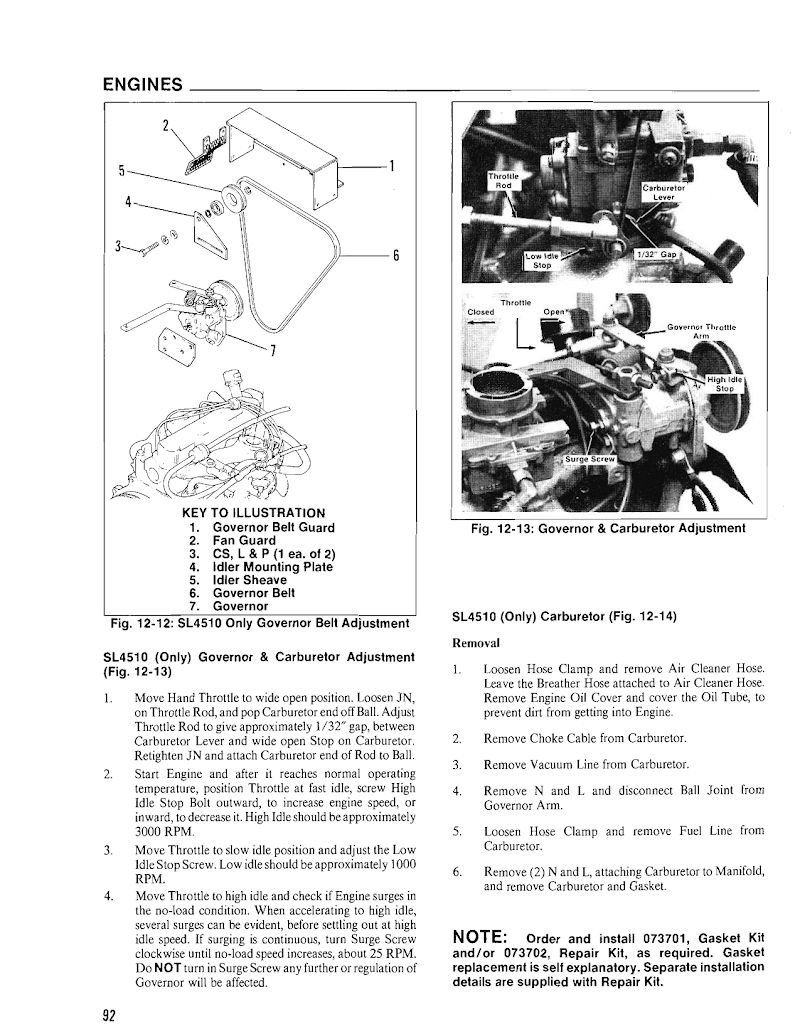
| Idle RPM & Gehl Governor Sync | Ford base engine mixture tune: 700–850 RPM · Gehl SL4510 installed specs: 1/32" WOT stop gap, Low Idle ~1000 RPM, High Idle ~3000 RPM, Surge Screw +25 RPM max |
Ford KSG-416 p. 3-03; Gehl 903931 Service Manual p. 92 (Fig. 12-13) |
🛒 Verified NAPA Shop Chemicals, Tools & Gasket Contingencies
Everything required for Track A (No-Kit Preservation Clean) and Track B (Master Overhaul) using your verified NAPA shop haul.
- NAPA Carburetor Parts Cleaner (1-Gal Dipping Basket): Safe for bare aluminum/cast-iron castings and brass jets after all gaskets, fiber washers, and non-metal parts are removed (Ford p. 3-04).
- Gumout / NAPA Mac's Jet Spray Carb & Choke Cleaner: Use with straw tube to backflush internal passages and verify discharge out the Main Nozzle
(51)and Idle Transfer Ports. - Non-Chlorinated Brake Cleaner & Compressed Air (40 PSI): For final residue-free drying and reverse-flushing passages.
- Penetrating Fluid (PB Blaster / Kroil): Essential for wetting the 6 bowl-to-intake screws
(18), 2 throttle-body screws(48), and rusted vacuum port fitting.
- Hollow-Ground Gunsmith / Carburetor Screwdrivers: Prevents cam-out on soft brass slots of the Idle Jet
(34), Main Jet(40), Well Vent(39), and Main Discharge Jet(51). - Nylon & Brass Detail Brushes ONLY: Clean exterior casting corrosion with nylon/brass bristles. Never insert steel wire, welding tip files, or drills into calibrated brass jets (Ford p. 3-04).
- 6-Inch Machinist Rule (1/32" / 1/64" Graduations): For setting the inverted float height to
1.484" (37.7 mm)/1-1/2" (38.1 mm)(FIG. 4).
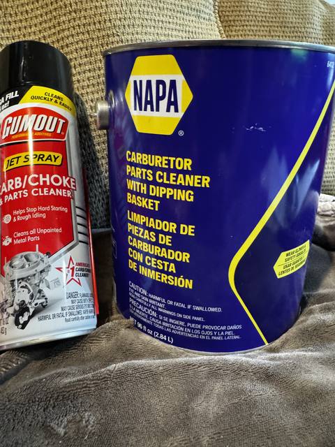
⚠️ Shop Supply Chemical & Brush Exclusions
- ❌ DO NOT Use Purple Power on Aluminum Castings: High-alkaline degreaser etches and darkens zinc/aluminum carburetor castings
(14, 46). - ❌ DO NOT Use the Stainless-Steel Brush or Welding Tip Cleaners: Keep the stainless brush from the 3-pack and any ridged steel tip cleaners away from brass jets and machined gasket faces.
- ✅ Gasket Contingency: Keep Fel-Pro Karropak sheet material and Permatex Aviation Form-A-Gasket No. 3 (never RTV silicone) on standby if a paper gasket weeps.
🛒 Verified Online Parts & Direct Order Links (Single-Pontoon Brass Float + Accelerator Pump + Master Kits)
Matched 100% to your 6-screw upper bowl gasket (IMG_3020), single-pontoon float (IMG_3042), cotter-pinned power valve (IMG_3028), and twin-post accelerator pump piston (IMG_3237–IMG_3243) on the Zenith Series 28 / 228 (13366 / 228 SAX9 · Ford KSG-416):
- 1. Single-Pontoon Solid Brass Float (100% Ethanol-Proof Replacement for Crumbling Black Float
IMG_3042/IMG_3245):- Genuine Zenith
C85-1Solid Brass Float ($63.33 — 32 in stock): Order Zenith C85-1 at Norfar Industrial - Mike's Carburetor Parts
FL1016Brass Float ($64.95 — In Stock): Order FL1016 (Zenith C85-1) at Mike's Carburetor Parts - Carbs Unlimited
C85-1Brass Float ($86.85): Order Zenith C85-1 at Carbs Unlimited
- Genuine Zenith
- 2. Replacement Accelerating Pump Plunger & Seal (Fixes Shredded Seal Ring in
IMG_3240–IMG_3242):- Mike's Carburetor Parts
AP454Standalone Accelerator Pump ($15.95 — In Stock): Exact2.224"overall length,0.576"cup diameter,1.966"stem with ethanol-ready cup seal — Order AP454 Accelerator Pump at Mike's Carburetor Parts - Mike's Carburetor Parts
K4042Complete Zenith 28/228 Rebuild Kit w/ Accelerator Pump ($39.95 — Best Value): Includes the new accelerator pump plunger, viton-tip fuel inlet needle & brass seat, gaskets, and clips — Order K4042 Kit w/ Pump at Mike's Carburetor Parts
- Mike's Carburetor Parts
- 3. Genuine OEM Zenith Series 28 / 228 Master Overhaul Kits (Includes Pump Shaft, Spring, L-Bar, Cotter Pin, Rubber Piston Seal Rings, Cotter-Pinned Power Valve & Exact 6-Screw Gasket
IMG_3020):- Genuine Zenith
K2206Master Carburetor Kit ($99.95 — 32 in stock): Order Genuine Zenith K2206 at Norfar - Genuine Zenith
K2002/KT-K2002Master Kit ($129.10–$139.00 — In Stock): Order Zenith K2002 at Norfar ($139.00) · Order KT-K2002 at Carbs Unlimited ($129.10) - Carbs Unlimited
CUK4146Zenith 228 Kit ($67.10 — 10+ in stock): Order CUK4146 Kit at Carbs Unlimited - Additional Genuine Zenith 228 Kits at Norfar: Zenith K2118 ($99.00) · Zenith K2215 ($109.00)
- Genuine Zenith
🏪 NAPA Counter Shopping & Part-Number Checklist (Bring Old Float + Pump Piston + Needle/Seat in a Ziploc Bag)
Give the counterman these exact Zenith Series 28 / 228 (#13366 / 228 SAX9 / 228 SBX9, Ford KSG-416 D3JL-N / D8JL-B) lookup numbers (plus Model 33 cross-refs B85-139 / B85-184 / K2226):
- 1. Single-Pontoon Replacement Float: Zenith
C85-1/ Mike'sFL1016Solid Brass Float (or cross-refB85-139/B85-184). - 2. Accelerator Pump & Rebuild Kit: Mike's
AP454Pump Plunger + Mike'sK4042or Genuine ZenithK2206/K2002(Gehl073702/073701; altCUK4146/K2226). - 3. Inline Fuel Filter + Clamps (Mandatory Debris Barrier): NAPA Gold
3001(1/4"hose) or NAPA Gold3002(5/16"hose) clear/metal inline filter + two mini stainless worm-gear clamps + 1 ft of SAE 30R7 / 30R9 fuel hose. - 4. Manifold Base Gasket & Sheet Stock: 2-Bolt SAE Carburetor Flange Gasket (
1-1/4"–1-1/2"bore,~2-11/16"bolt spacing) + 1 roll of Fel-Pro3060(1/32"Karropak) fuel-resistant gasket sheet. - 5. Aerosol Spray & Hardware Spares: 2 cans of Gumout Carb & Choke Cleaner (or NAPA Mac's
#4600) with red straw tubes + an assortment of1/16" x 1/2"Stainless/Brass Cotter Pins (for the bowl power valve stem & pump rod). ⚠️ NEVER use Permatex Red RTV Silicone (#81630) on the float or inside the fuel bowl!
As-Found Field Pathology: Prior-Owner Rigging Audit
Forensic inspection of your pre-removal photographs (IMG_1950–IMG_1987) revealed three non-factory field modifications on this Gehl SL4510 that caused erratic governor response and choke binding:
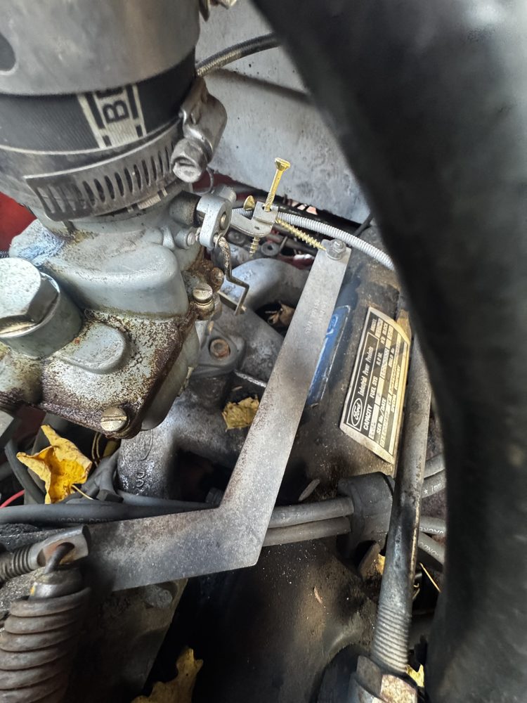
1. Torx Deck Screws in Choke Clamp (8 / 11)
Prior owner drove two yellow-zinc construction Torx wood screws into the Choke Bracket (13) and Swivel (8) above the Ford KSG-416 (2274E 1.6L) valve cover tag. Replace with proper machine screws (8, 11) and lock nut (12).
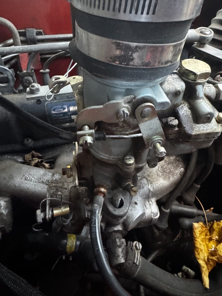
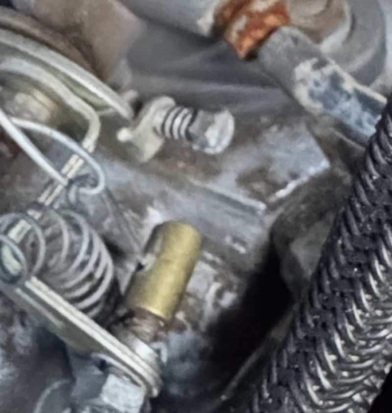
2. Bailing-Wire Governor Linkage Hack
Instead of the factory Gehl governor rod (074173 / 064102) and 10-32 ball joint (054885), twisted bailing wire and a set-screw brass barrel were rigged to Throttle Lever (64)—introducing lost motion and governor hunting.
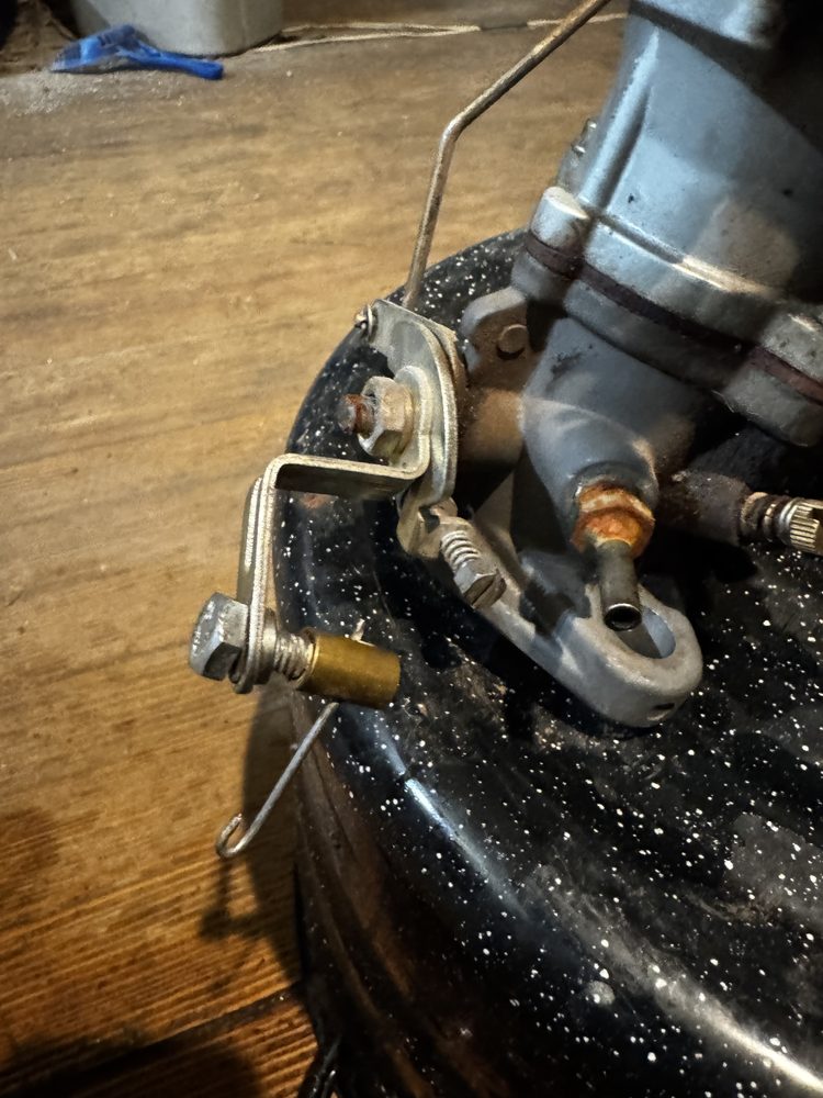
3. Throttle Body & Vacuum Fitting Corrosion
Close-up of Cast-Iron Throttle Body (57) showing Throttle Stop Screw (66), Idle Adjusting Needle (20) + Spring (21), Throttle Shaft Nut (60) + Lockwasher (61), and oxidized distributor vacuum fitting.
Tech Service OS: 360° Bench & Internal Bore Visual Atlas
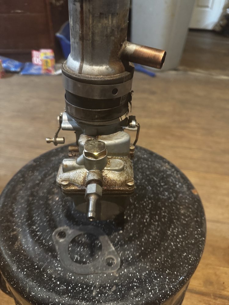
Top Air Horn & Filter Plug (15–17)
Shows the large brass Hex Filter Plug (15) housing the internal cylindrical Fuel Filter Element (17), barbed fuel inlet fitting, bowl cover screws (18), and 2-bolt Flange Gasket (69).
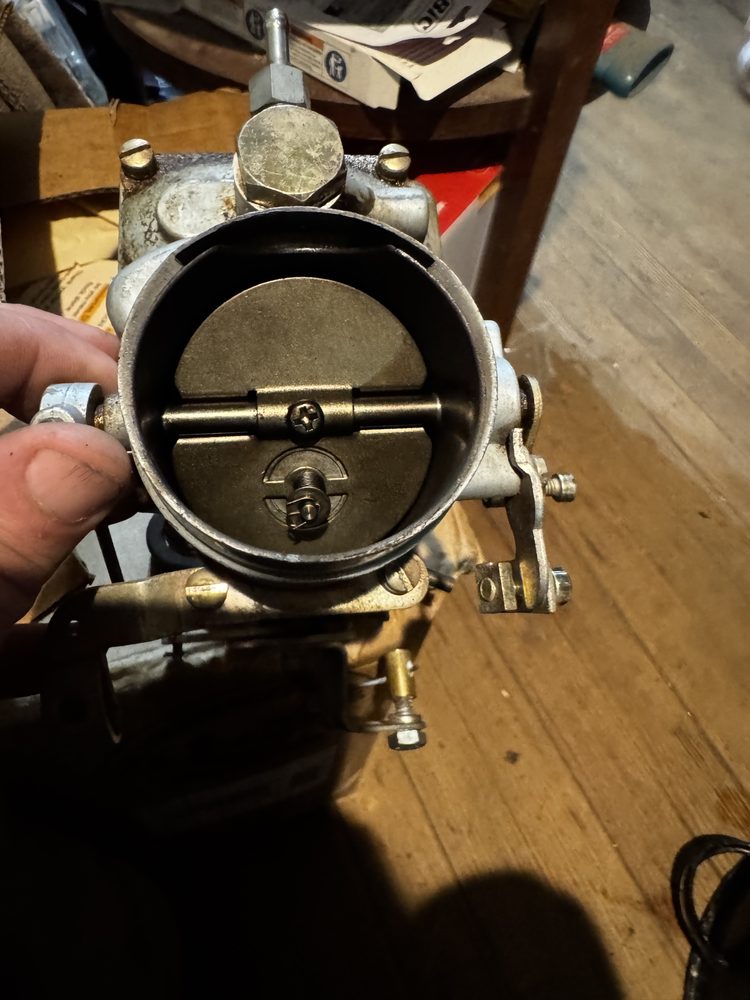
Choke Plate (2) & Relief Poppet
Looking down Air Intake Body (14) with Choke Plate (2) closed. Note the riveted Choke Screw (1) and the spring-loaded vacuum relief poppet valve (spring faces air entrance per Ford p. 3-05 Step 2).
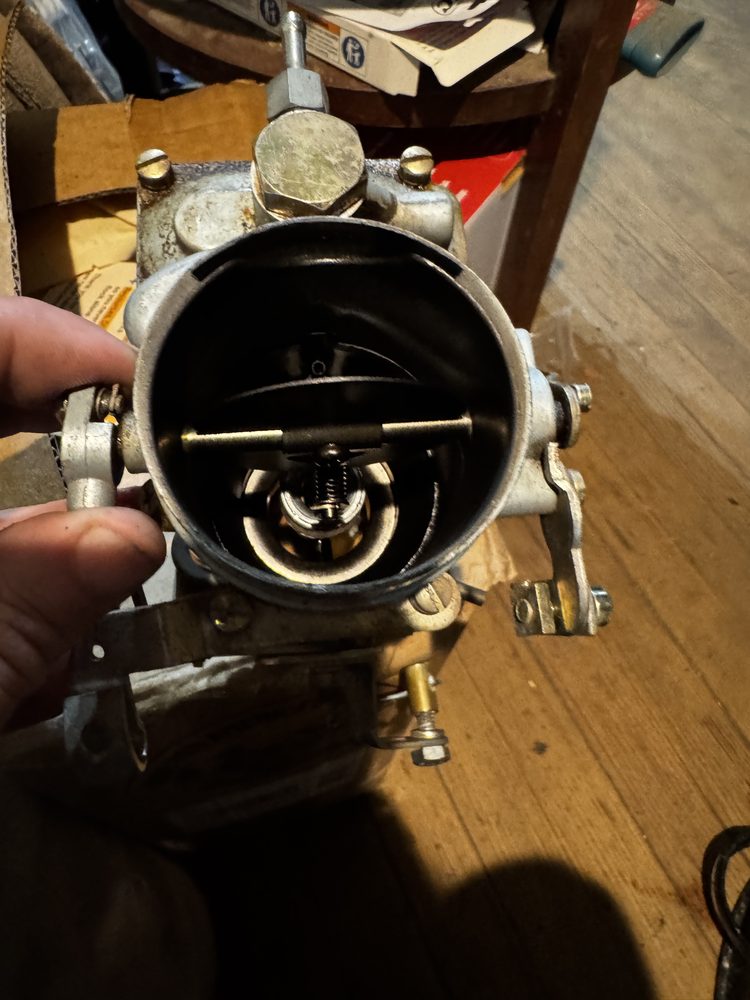
Open Throat: Venturi (50) & Nozzle (51)
Choke butterfly held open to reveal the concentric Primary Venturi (50) and angled brass Main Discharge Nozzle (51) centered in the main air stream.
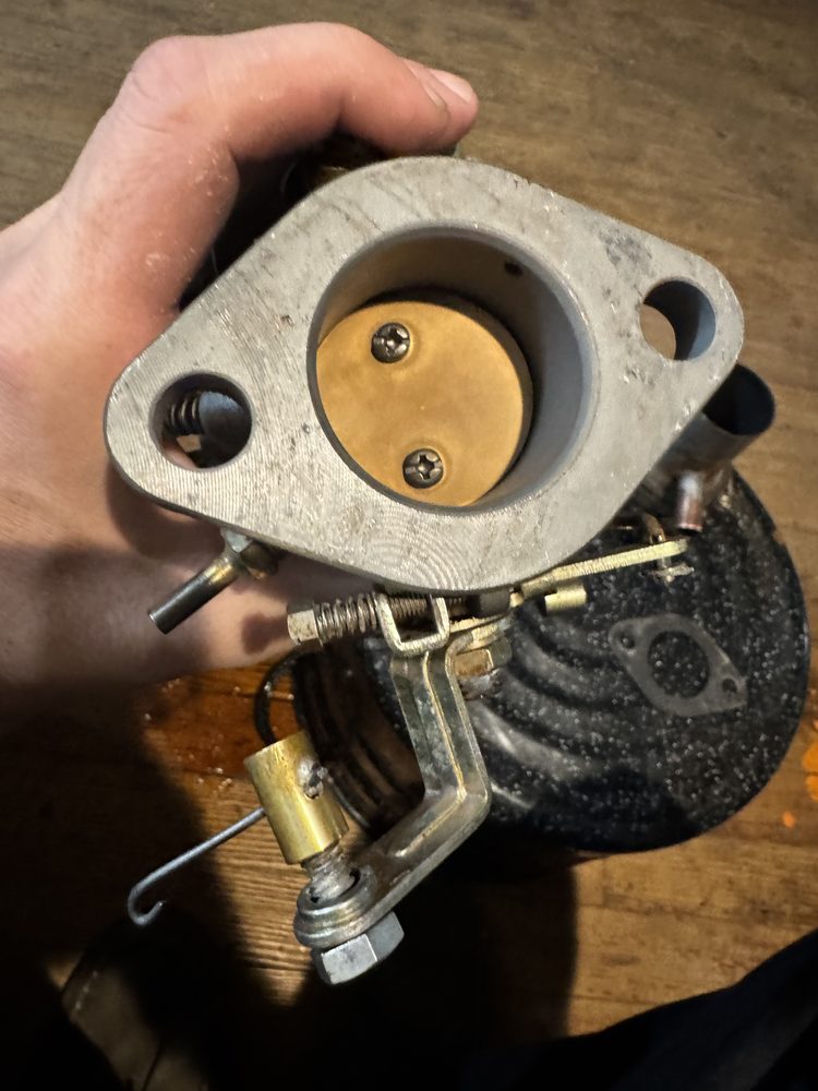
Base Flange (57) & Idle Transfer Port
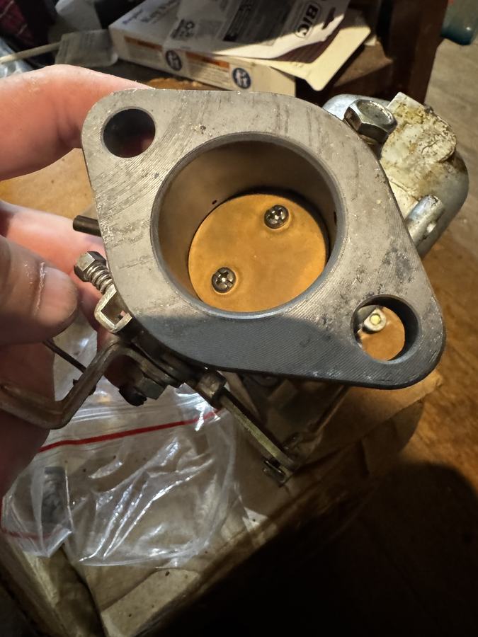
True underside view of Cast-Iron Throttle Body (57) and Brass Throttle Plate (56) with staked screws (55). Note the tiny drilled Idle / Off-Idle Transfer Port at the 9-o'clock bore wall!
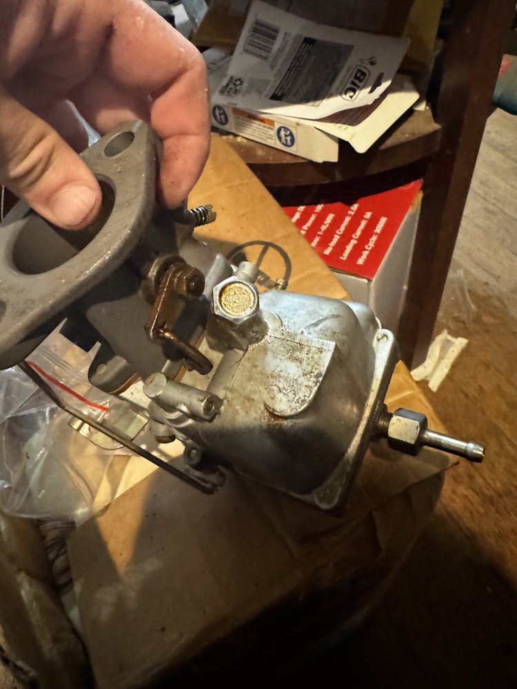
Fuel Bowl Underside & Drain Plug (45)
Bottom of Aluminum Fuel Bowl (46) showing the sintered bronze Bowl Drain/Vent Filter Plug (45), Main Passage Plug (53) boss, and Pump Lever (58) on Throttle Shaft (67).
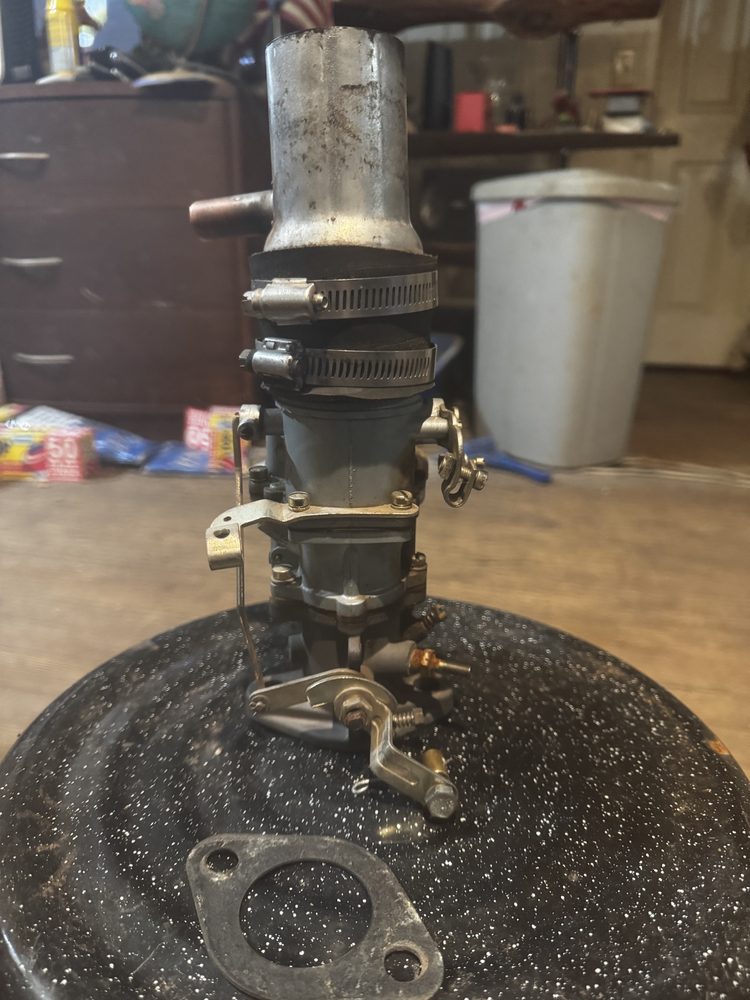
Pump Rod (29) 1/4-Stroke Groove
Shows Accelerating Pump Rod (29) with its hairpin retainer seated in the upper groove (1/4 stroke), connected via Pump Link (58) to Throttle Shaft (67).
Additional Multi-Angle Bench Views (Click to Expand)
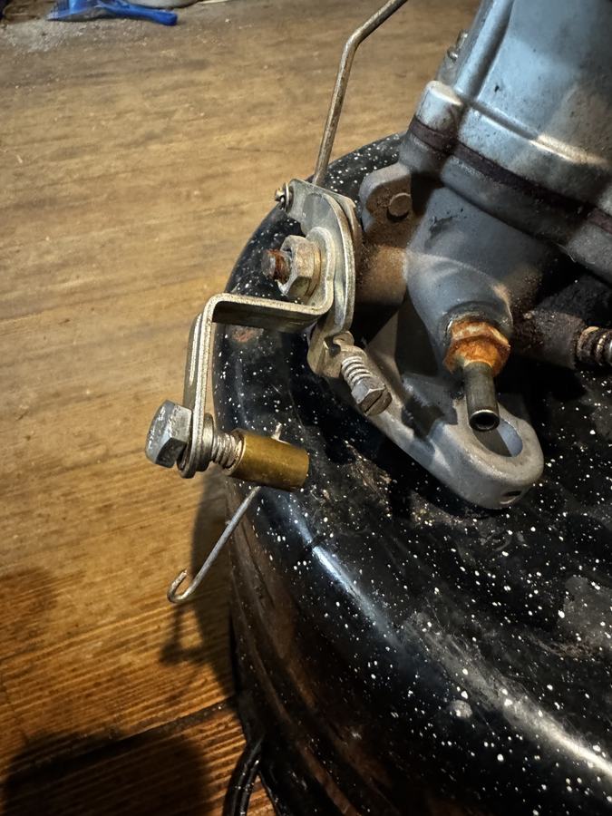
Idle & Stop Screw Alternate Angle
Alternate macro view of Throttle Stop Screw (66) and Idle Needle (20).
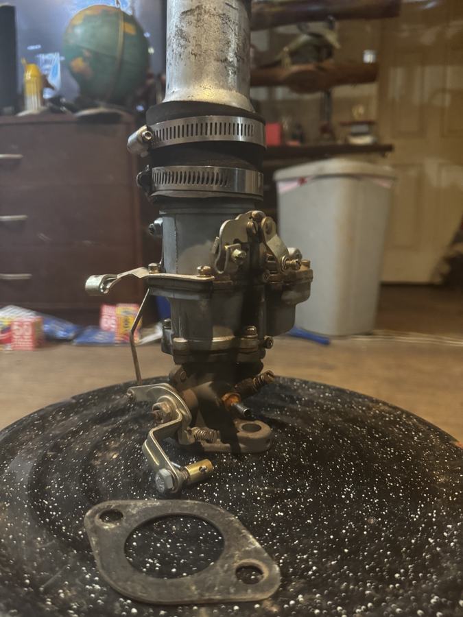
Linkage Profile Alternate Angle
Alternate view of Pump Rod (29) and Choke Bracket (13).
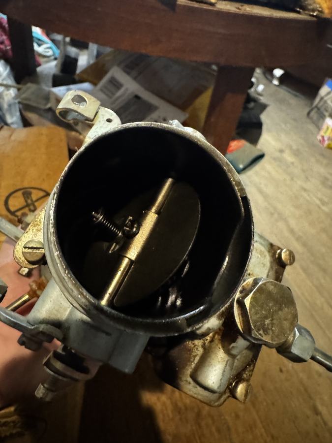
Choke Relief Poppet Macro
Close-up of spring-loaded vacuum poppet valve in Choke Plate (2).
Throttle Bore Progression Port
Close-up of the drilled idle progression orifice in Throttle Body (57).
Phase 1: Removal from the Ford KSG-416 Engine (Page 3-03)
- Disconnect Negative Battery Cable: Isolate the battery before opening any fuel fittings on the KSG-416 engine.
- Remove Air Intake Boot (3): Loosen the upper clamp and lift the rubber intake elbow clear of the Air Intake Body
(14). - Disconnect Fuel Inlet & Distributor Vacuum Line: Place shop towels beneath the barbed fuel inlet and steel distributor vacuum advance line (Ford p. 3-03 Removal Step 2). Catch residual fuel safely.
- Disconnect Throttle & Choke Linkages: Detach the governor control rod (Gehl P/N
074173/064102; replace prior-owner bailing wire) from Throttle Lever(64)and disconnect the choke cable from Choke Swivel(8)and Bracket(13). - Unbolt Carburetor from Manifold (781F-9425-ACA): Remove the two 1/2" base flange nuts, lift the carburetor straight off the manifold studs, and retrieve Flange Gasket
(69). - Seal the Intake Manifold Bore: Immediately cover the open intake manifold throat with a clean lint-free shop towel.
Phase 2: Bench Disassembly (Ford KSG-416 Page 3-04 & FIG. 6)
Follow the exact factory sequence below. Click any node in the interactive bench map to jump directly to and read aloud that step:
Verified to Ford KSG-411/416 Service Manual Pages 3-04 to 3-07 (
FIG. 5 & FIG. 6). The Air Intake Body (14) sits on top, the Aluminum Fuel Bowl (46) in the middle, and the Cast-Iron Throttle Body (57) at the manifold flange.
F100 Premortem Risk Matrix (Track A vs. Track B)
| Critical Component | Risk | Factory Manual Rule & Mitigation |
|---|---|---|
1. Float Pontoon Assembly (26) |
High | Lift Air Intake Body (14) straight up vertically so Float (26) and Accelerating Pump Piston (29) clear the Fuel Bowl (46) cavity without bending. |
2. Float Hinge Bracket & Axle (27) |
High | Push Float Axle (27) from the slotted side of the hinge bracket during removal; press in from opposite the slotted side during assembly (Ford p. 3-04 / 3-05). |
3. Idle & Nozzle Channel Bushings (47) |
Critical | DO NOT attempt to remove Channel Bushing (47) or Nozzle Bushing — pressed in at the factory (Ford p. 3-04 Fuel Bowl Disassembly Note). |
4. Staked Check Valves (30, 38) & Lead Plugs (36, 44) |
Critical | Track A Leave installed and test via Bench Pump Check (Ford p. 3-05). Track B Extract only with slide-hammer C161-5 when replacing with Kit 073702. |
5. Riveted Butterfly Screws (1, 55) & Idle Port Plug |
Critical | DO NOT remove the idle port plug from Throttle Body (57). Do not file staked Choke Screw (1) or Throttle Screws (55) unless replacing worn shafts. |
2.1 Disassembly & Removal of Air Intake Body (14) — Ford Page 3-04
- Remove the large brass Hex Filter Plug (15), Fiber Washer (16), and cylindrical Fuel Filter Screen Element (17) from the top of Air Intake Body (14).
- Record Pump Stroke Groove: Note which groove on Accelerating Pump Rod (29) holds the hairpin retainer (as-found on your unit: upper groove = 1/4 stroke; lower groove = 1/2 stroke). Remove the six bowl-to-intake screws (18) and lockwashers.
- Vertical Seam Split: Raise Air Intake Body (14) slightly. If Bowl Gasket (28) adheres to both castings, coax it loose with a flat razor blade held parallel to the machined flange, then lift Air Intake Body (14) straight up vertically so Float (26) and Pump Piston (29) clear the bowl without bending.
- Invert Air Intake Body (14) on the bench and carefully lift off Bowl-to-Intake Gasket (28).
- Press a small screwdriver against Float Axle (27) from the slotted side of the hinge bracket. Remove Float Assembly (26) and the tapered Fuel Valve Needle (part of 22).
- Remove brass Fuel Valve Seat (22) and Fiber Washer (23) using a wide hollow-ground blade (Zenith tool
C161-85). Track B Only Only file and remove staked Choke Plate Screw (1) and Choke Plate (2) if replacing bent Choke Shaft (7).
2.2 Separate Fuel Bowl (46) and Cast-Iron Throttle Body (57) — Ford Page 3-04
- Crack loose the lower Main Passage Hex Plug (53) while you still have firm leverage on the assembled body.
- Loosen the Throttle Shaft Nut (60) securing Pump Lever Link (58) (5/16" wrench / Zenith
C161-25). - Remove the two screws (48) and lockwashers attaching Fuel Bowl (46) to Cast-Iron Throttle Body (57).
- Separate Fuel Bowl (46) from Throttle Body (57) just enough to thread off Nut (60) and Lockwasher (61).
- Slide Pump Lever Link (58) off the flatted end of Throttle Shaft (67) and out of Accelerating Pump Rod (29).
- Lift Fuel Bowl (46) completely clear of Cast-Iron Throttle Body (57).
- Remove Primary Venturi (50) and Throttle Body Gasket (54) (note the metal-reinforced ring hole in Gasket 54 that surrounds Idle Channel Bushing 47).
2.3 Disassembly of Fuel Bowl (46) & Brass Metering Jets — Ford Page 3-04
- Using hollow-ground screwdrivers, remove the Idle Jet (34), Accelerating Jet (37), and Well Vent Jet (39) from the top surface of Fuel Bowl (46). Remove the Main Jet (40) + Fiber Washer (41) from inside the bottom of the bowl, and remove Main Passage Plug (53) + Washer (52) and angled Main Discharge Nozzle (51) from the outside lower boss. Inspect the sintered bronze Bowl Drain Plug (45) at the base of the bowl.
- Track A (No-Kit) Leave the press-fit Air Vent Check Valve (30) (which retains Brass Washer 31, Square Weight 32, and Refill Check Ball 33) and Pump Check Valve (38) installed in their bores; verify them via the Bench Pump Action Check in Phase 3. Track B (Master Kit 073702) Extract Air Vent Check Valve (30) and Pump Check Valve (38) using inverse slide-hammer
C161-5, then invert the bowl over a tray to catch Retainer (31), Square Weight (32), and Steel Ball (33). - CRITICAL FACTORY WARNING: DO NOT attempt to remove Idle Channel Bushing (47) or the nozzle bushing. They are press-fit at the factory and are never removed for carburetor overhaul (Ford p. 3-04).
2.4 Disassembly & Inspection of Cast-Iron Throttle Body (57) — Ford Page 3-04
- Warning: DO NOT remove the pressed idle port plug from the side of Throttle Body (57).
- Record As-Found Idle Mixture Turns: Gently turn brass Idle Adjusting Needle (20) clockwise (IN) while counting exact 1/4-turns until it lightly touches its seat. Record this number, then unscrew and remove Needle (20) and Spring (21).
- Track A Leave staked Throttle Plate Screws (55) and Brass Throttle Plate (56) assembled; clean the bore and drilled Idle Transfer Port (visible at the 9-o'clock bore wall in
carb-flange.jpeg) in place. Track B Only file riveted ends of Screws (55) flat to remove Throttle Plate (56) and Shaft (67) if reaming for new bushings (C9-55/C9-56).
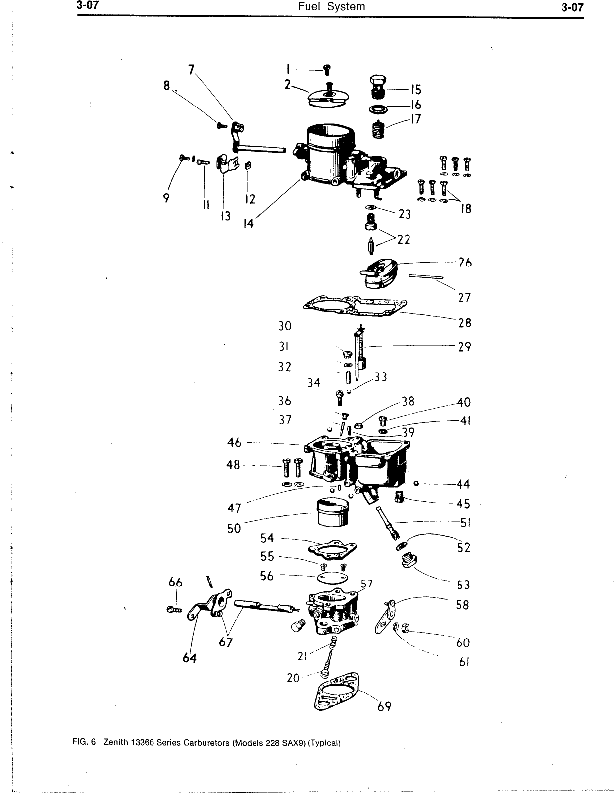
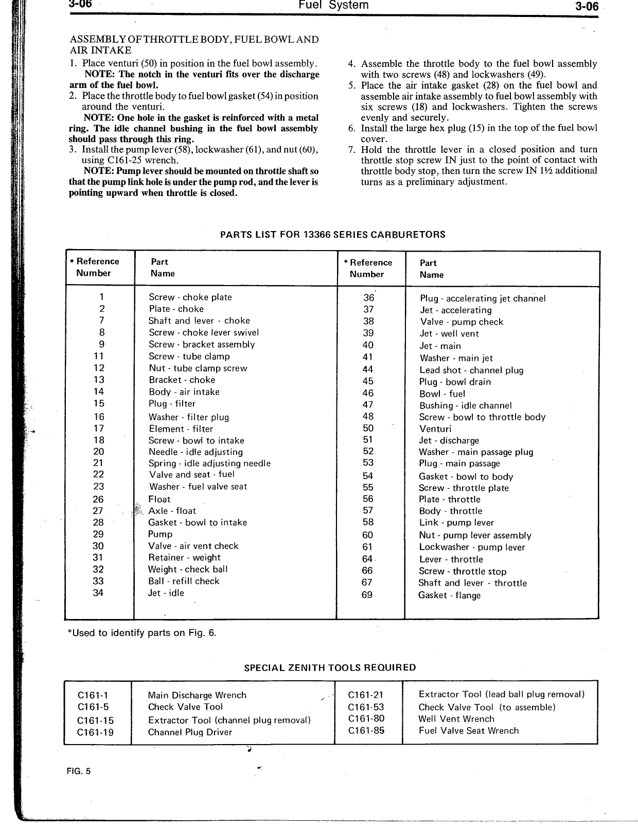
🔍 Interactive FIG. 6 Reference Callout Explorer (Items 1–69)
Search by callout number (1–69) or part name, filter by casting group, or click any part to jump to its procedure step:
Live Bench Teardown & Root-Cause Forensics (IMG_3009–IMG_3043 & IMG_3237–IMG_3245)
Complete 42-photo forensic inspection of your actual bench teardown—documenting Smoking Gun #1: the fuel-logged cellular nitrile float (IMG_3042, IMG_3245), Smoking Gun #2: the split two-piece Accelerating Pump Piston Seal Ring (IMG_3237–IMG_3244), the Critical Permatex #81630 Red RTV Warning (IMG_3243, IMG_3245), and the 7 internal jets, valves, and cast features.
🚨 Smoking Gun #1 (IMG_3042 & IMG_3245): Fuel-Logged Black Composite Float & Why Red RTV Cannot Go in the Bowl
- 1. Why It Stopped Leaking on the Bench (
IMG_3245) After Weeping Gas inIMG_3042: Your black molded cellular nitrile (Nitrophyl) float has broken closed-cell skin on its lower curve. Once removed from the bowl, the volatile surface gasoline evaporated out of the outer pores so it feels dry when squeezed—but the instant it is submerged back into pressurized gasoline, fuel re-enters the open pores, weights the float down, holds the 2-piece Fuel Inlet Needle open, and floods the engine. - 2. ⛔ CRITICAL WARNING — DO NOT Put Permatex
#81630Red RTV Silicone in the Fuel Bowl (IMG_3243,IMG_3245): InIMG_3245, red RTV silicone was dabbed onto the crumbling side of the black float. Permatex High-Temp Red RTV (#81630) is NOT fuel-resistant: submerged in gasoline, silicone RTV swells into jelly and sloughs off in rubbery strings that will permanently plug your bottom Main Jet (IMG_3028), cotter-pinned Power Valve, and Idle Jet. Peel all red RTV off immediately! - 3. Direct Bolt-In Permanent Fix: Order the 100% ethanol-proof Single-Pontoon Solid Brass Float — Zenith
C85-1($63.33 at Norfar) or Mike'sFL1016($64.95 at Mike's Carburetor Parts).
🔍 Smoking Gun #2 (IMG_3237–IMG_3244): Shredded Accelerating Pump Piston Seal Ring
- 1. What the Two Curved Black Pieces Are (
IMG_3241,IMG_3242): Pulling the twin-post Accelerating Pump assembly out of its cylinder bore (IMG_3237,IMG_3238) revealed that the black Buna-N elastomer piston seal ring seated in the narrow lower groove of the brass plunger head (IMG_3240) rotted from ethanol fuel and snapped cleanly into two crescent-shaped halves (IMG_3241)! - 2. Explains the Bore Debris (
IMG_3038) & Throttle Stumble: Without that dynamic piston ring seal (IMG_3243), the brass pump piston cannot build pressure on the downstroke—fuel simply bypasses up the cylinder wall while shedding black rubber slivers directly into the teardrop pump intake port (IMG_3038) and bowl floor (IMG_3013,IMG_3015). - 3. Direct Replacement Options: Order the standalone ethanol-ready Accelerator Pump Plunger
AP454($15.95) (Mike's Carburetor Parts), the Complete Rebuild Kit w/ PumpK4042($39.95) (Mike's K4042), or the Genuine OEM Zenith Master KitK2206($99.95) /K2002($139.00) (Norfar K2206), which includes the exact brass piston seal rings, shaft, spring, L-bar, and cotter pin shown in your magnetic dish (IMG_3244).
🔬 7-Point Internal Jet, Valve & Casting Anatomy (Mapped to Your Teardown Photos)
| Internal Component & Photo Key | Location in Casting | Bench Service Rule & Tool Fit |
|---|---|---|
1. Bottom Slotted Main Metering Jet (IMG_3028) |
Deep floor of Fuel Bowl (center-right in IMG_3028) |
Unscrew with a snug 1/4" hollow-ground flathead (IMG_3031) after soaking in penetrant; backflush passage to Main Nozzle. |
2. Cotter-Pinned Vacuum Power / Economizer Valve (IMG_3015, IMG_3028) |
Raised hex-base brass tower inside Fuel Bowl floor (actuated by upper Vacuum Piston in IMG_3030) |
DO NOT pull the tiny cotter pin! Unscrew the entire hex-base valve assembly as a unit or press its center stem down during Gumout spray flushing. |
3. Recessed Slotted Idle Jet (IMG_3028, IMG_3029) |
Recessed cylindrical well between Fuel Bowl and Venturi throat (8 o'clock in IMG_3029) |
Unscrew with the largest precision flathead blade from the yellow General S605 set (IMG_3012) that spans 100% of the brass slot width. |
4. Booster Venturi Nozzle Jet (IMG_3014, IMG_3029) |
Center of the cast discharge bridge spanning the Venturi bore (6 o'clock in IMG_3029) |
Unscrew carefully with a matched precision flathead driver and flush the horizontal bridge passage until Gumout sprays cleanly into the throat. |
5. Cast Primary Booster Venturi Spout (IMG_3040, IMG_3041) |
Center of the main throat casting | DO NOT PRY OR PULL! Cast as one structural piece with the horizontal discharge bridge (IMG_3041); prying will snap the bridge. |
6. Flush Threaded Brass Deck Insert (IMG_3035, IMG_3036) |
Top machined deck of Fuel Bowl at 4 o'clock next to Venturi throat | DO NOT UNSCREW! Factory-installed permanent brass passage bushing; spray Gumout + air straight through its center hole. |
7. Wide-Slotted Brass Fuel Inlet Seat (IMG_3043) & 2-Piece Needle (IMG_3042) |
Underside of Upper Air Intake Horn next to 5/8" hex fuel inlet fitting | Unscrew wide-slotted seat (IMG_3043) with a broad flathead blade; flush screen/passage behind it and inspect the spring-damper needle tip (IMG_3042). |
📸 27-Plate Curated Bench Teardown Atlas (IMG_3010–IMG_3043 & IMG_3237–IMG_3245 — Click Any Photo to Inspect Full Screen)
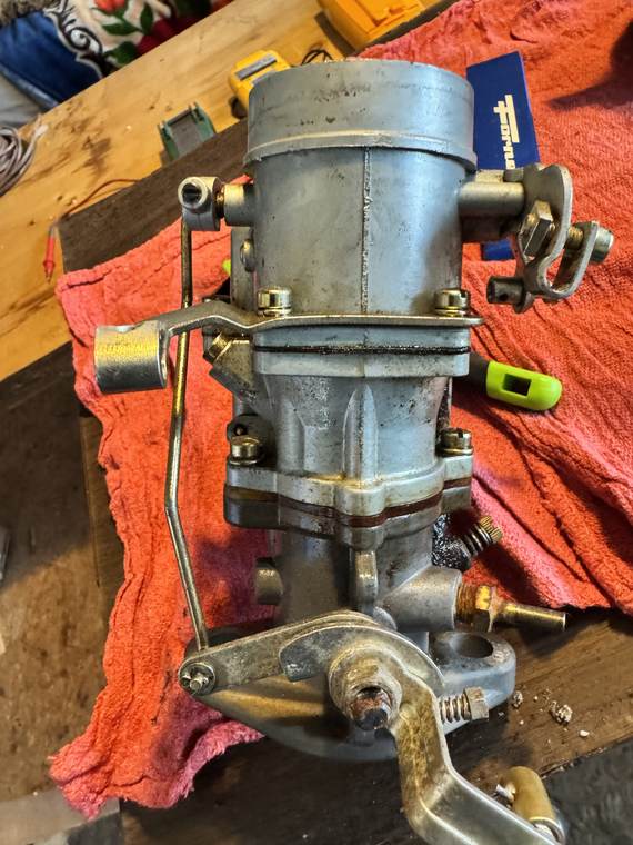
1. Pre-Split Exterior Profile (IMG_3010)
Shows the 4 yellow-chromate Phillips/slotted upper air-horn screws, 2 lower throttle-body screws, angled brass Idle Mixture Needle + spring, vacuum fitting, and cotter-pinned pump link rod.
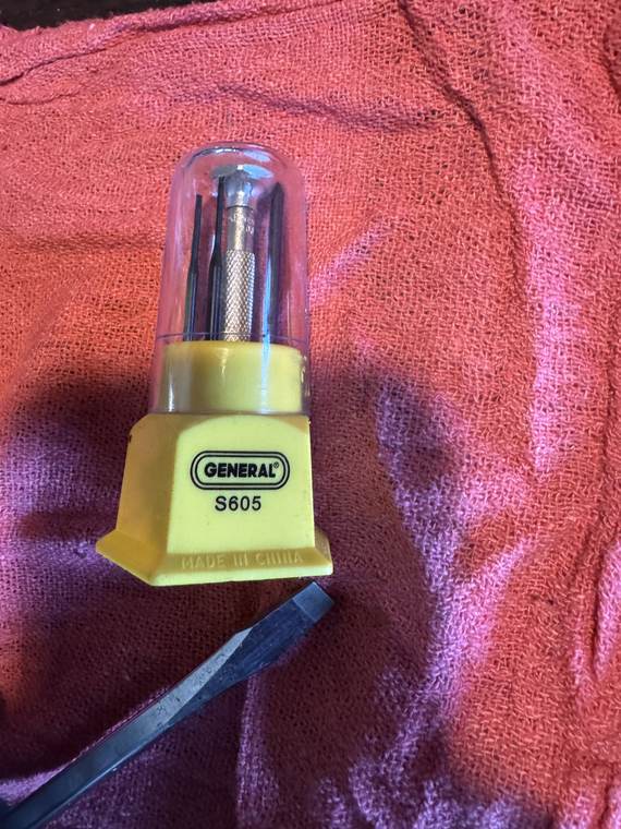
2. Driver Selection: Precision vs. 1/4" Blade (IMG_3012)
Use the wide flathead for the exterior casting screws and wide-slotted inlet seat (IMG_3043), and the largest precision flathead from the yellow General S605 set for the recessed Idle & Nozzle Jets.
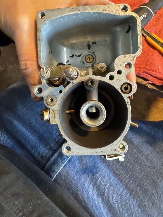
3. As-Opened Bowl Floor Debris (IMG_3013)
First look inside the open Fuel Bowl immediately after lifting the air horn: note the black float-foam crumbs lying directly around the slotted brass Main Jet at the bottom of the bowl.
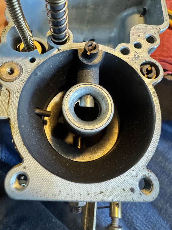
4. Throat Bore, Nozzle & Bleed Tube (IMG_3014)
Looking straight down the main throat at the concentric cast Booster Venturi, horizontal discharge bridge, slotted Nozzle Jet (9 o'clock), recessed Idle Jet (11 o'clock), and brass bleed tube (6 o'clock).
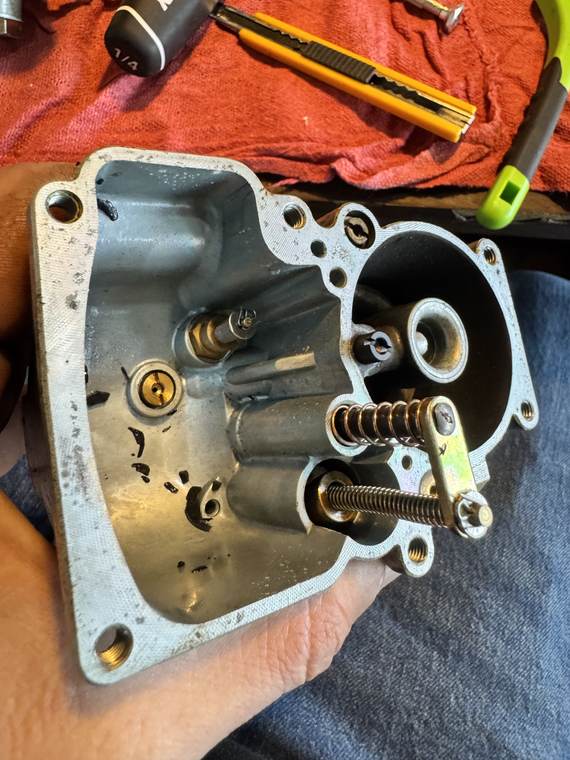
5. Bowl Floor & Power Valve Macro (IMG_3015)
Angled close-up confirming black composite float crumbs scattered across the wet aluminum floor beside the bottom Main Jet, cotter-pinned Power/Economizer Valve, and twin-post Accelerating Pump.
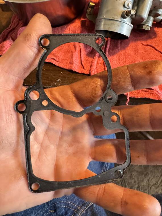
6. 100% Intact Upper Bowl Gasket (IMG_3020)
The upper Bowl-to-Air-Horn paper gasket lifted off cleanly with zero tears or delamination—ready for flat dry storage and Track A reuse if needed.
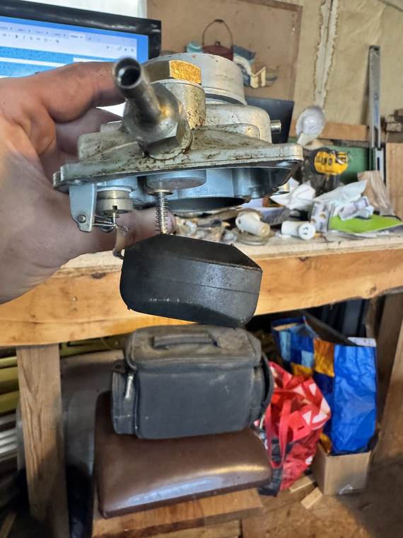
7. Inverted Air Horn & Float Check (IMG_3022)
Holding the Upper Air Intake Horn vertically on the bench to inspect the black composite float pontoon, spring-loaded brass Vacuum Power Piston, and Fuel Inlet Valve before pulling the hinge pin.
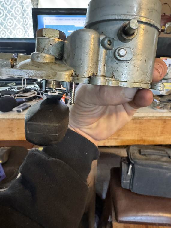
8. Float Tang & Inlet Needle Interface (IMG_3025)
Macro view of how the brass float hinge arm rests on the top damper pin of the Fuel Inlet Needle inside the wide-slotted Brass Seat, right beside the spring-loaded Vacuum Piston.
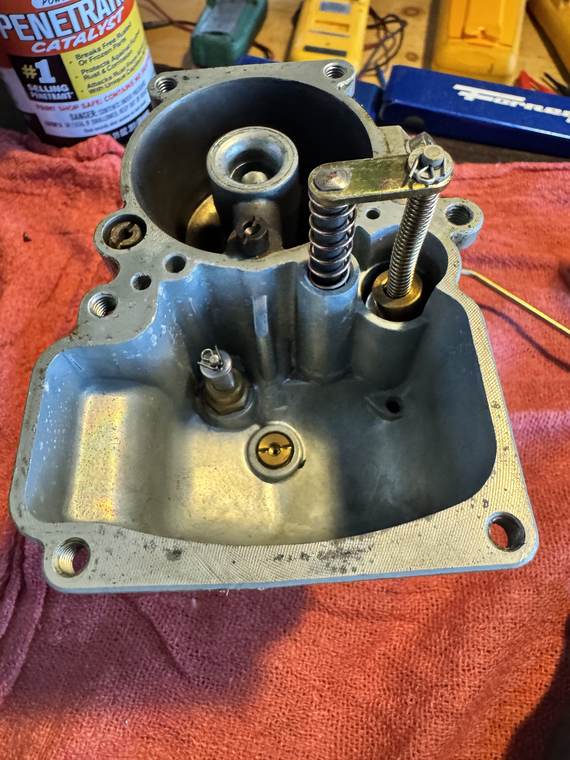
9. Bowl Floor After Initial Wipe (IMG_3028)
Compare with IMG_3013/3015: after wiping away the loose black float crumbs, the slotted bottom Main Jet, hex-base cotter-pinned Power Valve, and recessed Idle Jet are clearly visible.
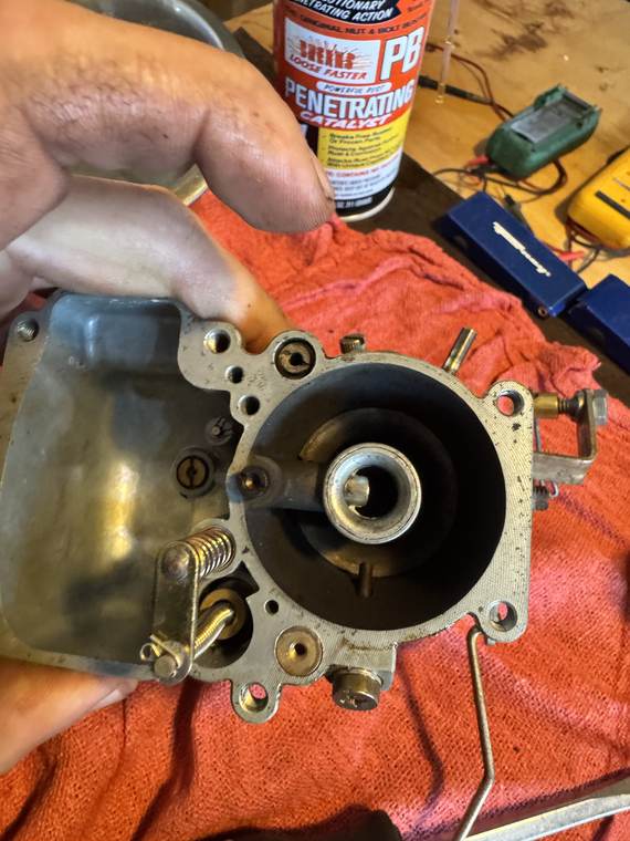
10. Upper Deck Jet Map (IMG_3029)
Overhead map of the middle casting deck: Booster Nozzle Jet at 6 o'clock on the bridge, recessed Idle Jet at 8 o'clock, and pressed threaded brass insert at 4 o'clock.
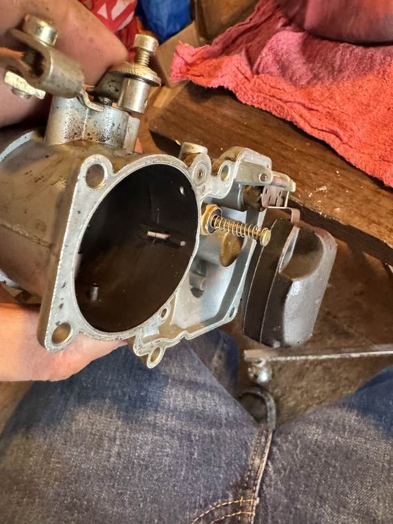
11. Air Horn Vacuum Piston & Bleed Tubes (IMG_3030)
Shows how the spring-loaded brass Vacuum Piston aligns with the molded clearance pocket in the float and reaches down to actuate the cotter-pinned Power Valve in the bowl.
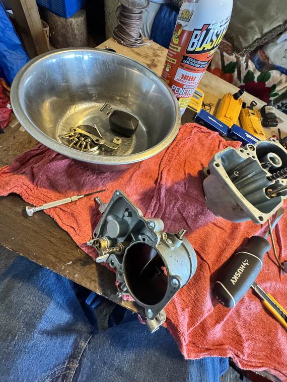
12. Organized Bench Split & Parts Dish (IMG_3031)
Full bench layout after removing the float axle pin: float, needle, choke bracket, and screws safely staged in the stainless magnetic dish beside the Husky 1/4" and precision drivers.
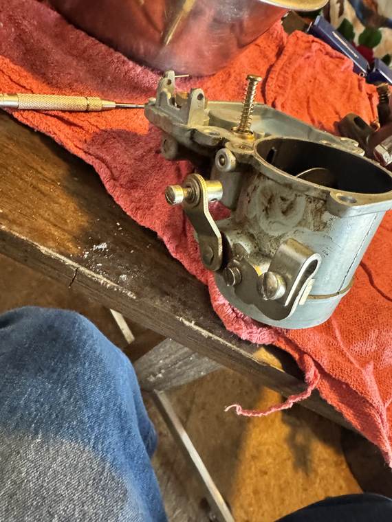
13. External Choke Cable Clamp (IMG_3033)
Leave Intact: This external screw on the Upper Air Horn secures the Choke Cable Clamp & Swivel Lever—it does not hold any internal passage and does not need to be removed.
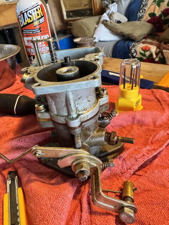
14. Intact Lower Insulator Gasket (IMG_3034)
Track A Preservation Rule: The thick reddish-brown lower Throttle-Body-to-Bowl insulator gasket is 100% sealed. Unscrew the brass Idle Mixture Needle (left), count turns, and backflush through its port without splitting this seam!
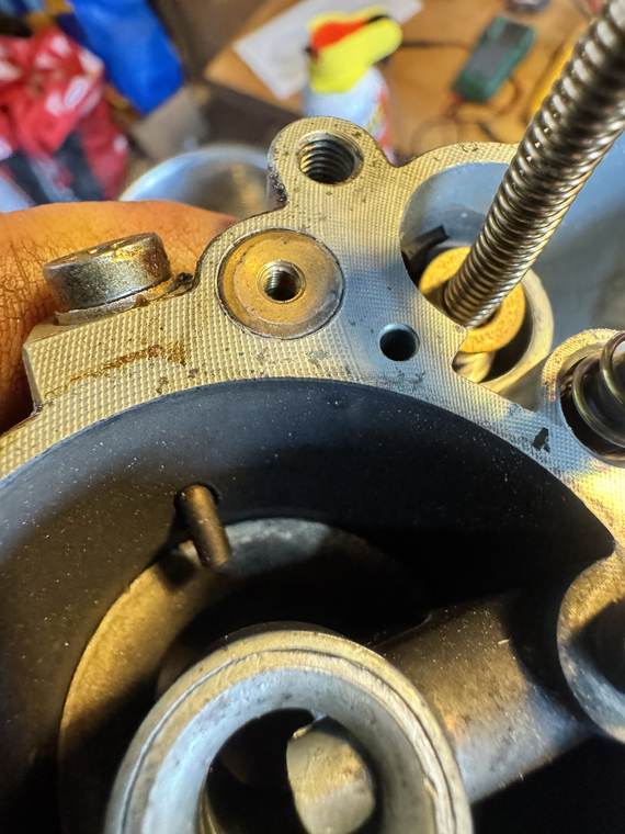
15. Flush Brass Insert & Pump Tube (IMG_3035)
DO NOT Unscrew: The flush threaded brass insert on the deck has no screwdriver slot—it is a permanent factory passage bushing. Note the brass accelerating-pump discharge tube inside the throat wall at 5 o'clock.
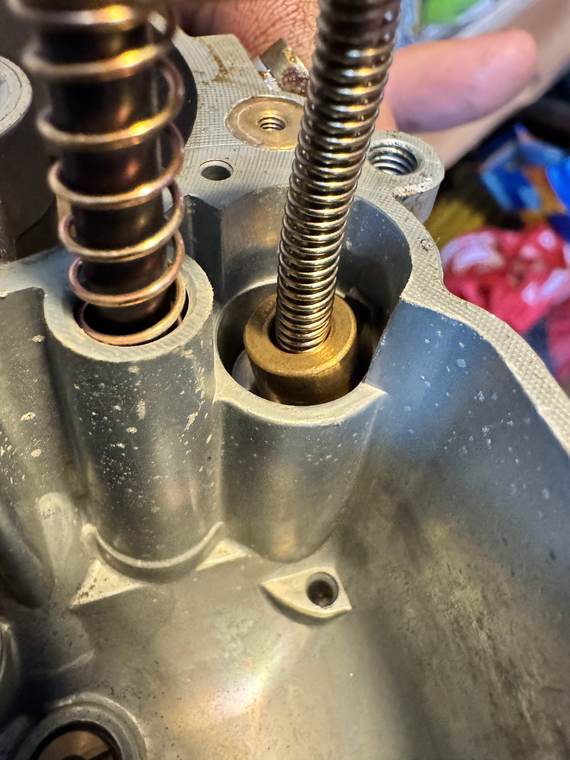
16. Pump Bore & Teardrop Intake Port (IMG_3037)
High-resolution view of the twin-post Accelerating Pump assembly and the recessed teardrop-shaped fuel intake port on the inner wall of the float bowl that feeds the pump cylinder.
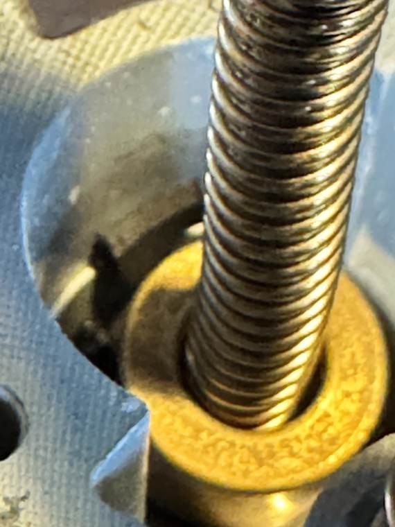
17. Forensic Catch: Flake in Pump Bore (IMG_3038)
Critical Inspection Catch: Look at 6–8 o'clock in the crescent gap between the brass pump sleeve and aluminum bore wall—a black float-foam flake is wedged right at the pump intake! Flush out completely.
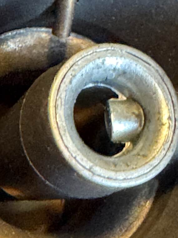
18. Cast Primary Booster Venturi (IMG_3041)
DO NOT PRY: Extreme macro proving the center Primary Booster Venturi spout is cast as one piece with the horizontal discharge bridge. Clean in place after unscrewing the brass Nozzle Jet.
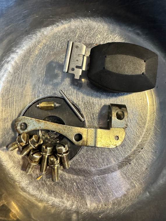
19. Smoking Gun: Fuel-Logged Float (IMG_3042)
Root Cause Confirmed: The black composite float weeps gasoline when squeezed, and its rotting lower-left edge (7–8 o'clock) is shedding the exact black crumbs found in IMG_3013, 3015, and 3038. Next to it sits the 2-piece spring-damper Fuel Inlet Needle.
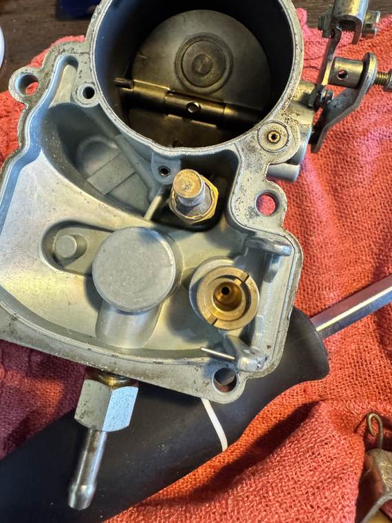
20. Wide-Slotted Brass Fuel Inlet Seat (IMG_3043)
Looking straight down into the wide-slotted Brass Fuel Inlet Seat on the Upper Air Horn beside the 5/8" hex fuel inlet fitting. Unscrew with a wide flathead driver to flush any trapped float crumbs behind the seat.
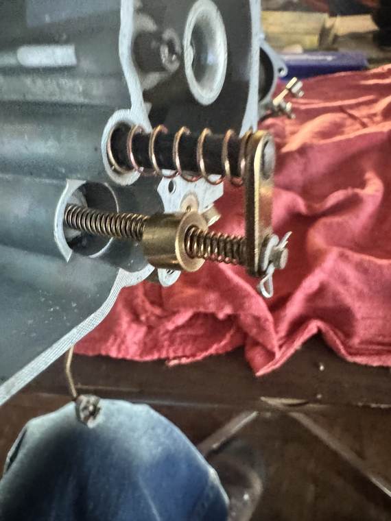
21. Extracting Twin-Post Accelerating Pump (IMG_3237)
Lifting the twin-post Accelerating Pump assembly out of the middle casting: shows the outer guide rod with copper return spring, flat yellow-chromate bridge bar, cotter pin + washer, brass collar, and inner coil spring.
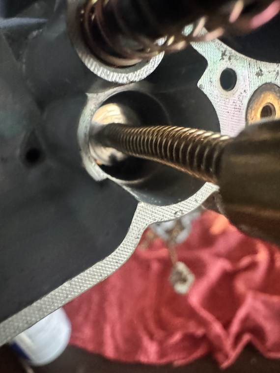
22. Pump Cylinder Bore & Brass Plunger (IMG_3238)
Looking straight down into the aluminum Accelerating Pump well as the brass plunger head and internal spring emerge from the bore beside the bottom Main Jet and Power Valve.
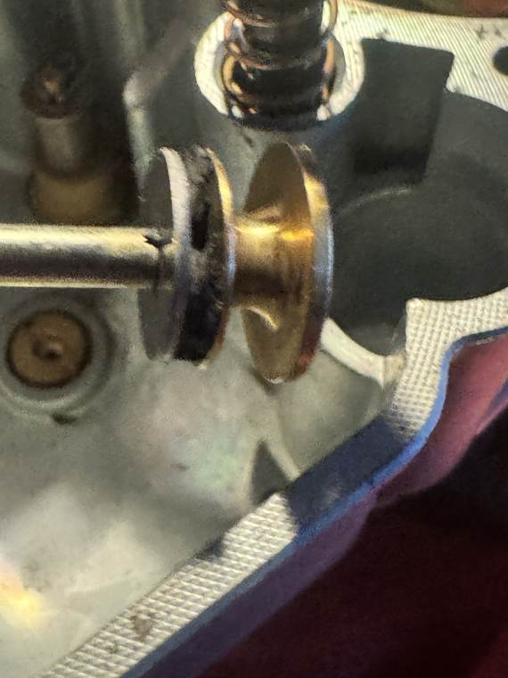
23. Shredded Seal in Brass Piston Groove (IMG_3240)
Extreme close-up of the brass Accelerating Pump Piston head: the black nitrile elastomer seal ring inside the narrow lower groove is shredded and missing half its circumference.
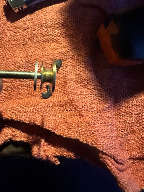
24. Smoking Gun #2: Broken Pump Seal Halves (IMG_3241)
Second Root Cause Confirmed: Here are the two broken crescent-shaped halves of the rotted black Accelerating Pump Piston Seal Ring resting right on top of the brass plunger spool.
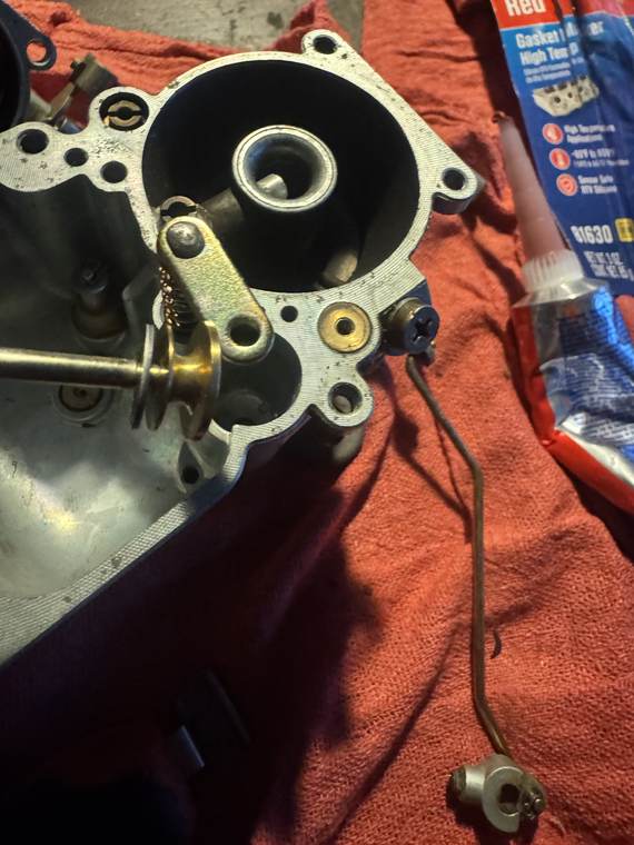
25. Bare Brass Pump Piston & Empty Groove (IMG_3243)
With both broken rubber seal halves removed, the empty machined seal groove at the base of the brass pump plunger is clearly visible above the open pump cylinder well.
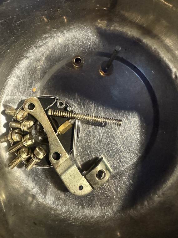
26. Staged Pump & Valve Hardware in Dish (IMG_3244)
Complete small-parts inventory safely staged in the magnetic dish: long pump coil spring, brass guide collar, tiny cotter pin + flat washer, 2-piece hex fuel inlet needle, float axle pin, choke bracket, and 6 bowl screws.
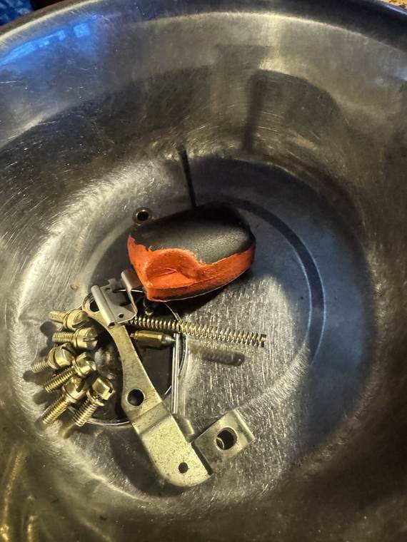
27. ⛔ WARNING: Remove Red RTV From Float (IMG_3245)
DO NOT SUBMERGE IN GASOLINE: Permatex #81630 Red RTV dissolves and swells into jelly in gasoline, which will clog every jet in the bowl. Replace with solid brass float Zenith C85-1 / FL1016.
| Component & Bench Photo | Pre-Dip Prep (Do This First) | Exact Soak Time in NAPA Dip Bucket | Post-Soak Rinse & Dry Rule |
|---|---|---|---|
| 1. Aluminum Fuel Bowl (46), Upper Air Horn (14) & Conical Primary Venturi (50) ( IMG_3805, IMG_3821, IMG_3822, IMG_3825) |
Unscrew the 4 brass jets/seats marked with AMBER [UNSCREW] ARROWS in Plates A, B & C so solvent reaches the hidden passages behind their threads. Leave the cotter-pinned Power Valve & Vacuum Piston in place. | ⏱️ 20 to 30 Minutes ( 45 Minutes Max — do not leave aluminum overnight or the caustic top layer will darken/pit the casting) |
Lift basket, drain 60 seconds, blast every drilling with Gumout Jet Spray, rinse in warm water or mineral spirits, and blow bone-dry in reverse direction with compressed air. |
| 2. All Unscrewed Brass Jets, Seats & Plugs (Main Jet 40, Recessed Idle Jet 34, Bridge Nozzle Jet, Inlet Seat 22, Lower Hex Plug 53, Idle Needle 20 + Spring 21) |
Peel off and set aside all red/grey Fiber Washers (16, 23, 41, 52) so they do not turn to mush in the basket. |
⏱️ 20 to 30 Minutes (Place inside the small mesh strainer basket at the center of the NAPA bucket) |
Flush with Gumout aerosol and blow out with compressed air. Hold every jet up to a bright light to confirm a crisp round bore—NEVER poke wire or drills through brass jets! |
| 3. Lower Cast-Iron Throttle Body (57) ( IMG_3808, IMG_3809) |
Turn Idle Adjusting Needle (20) gently IN while counting turns to lightness, then unscrew Needle (20) & Spring (21) completely so the idle transfer port is wide open. |
⏱️ Gumout Aerosol + Air Only (or 10–15 Minutes Max in Dip Bucket) |
Blow completely dry with compressed air immediately, then put 2 drops of clean motor oil onto both ends of Throttle Shaft (67) so bare cast iron cannot flash-rust. |
| 4. Top Brass Hex Plug (15) with White Nylon Filter Screen (17) ( IMG_3810 — see Plate E) |
Leave Fiber Washer (16) & White Nylon Screen (17) out of the dip bucket! |
⛔ 0 MINUTES — NEVER DIP! (Immersion solvent softens and warps white nylon mesh) |
Clean the white nylon screen using a quick 2-second blast of Gumout aerosol spray from the inside out, followed by low-pressure compressed air. |
| 5. New Brown Leather-Cup Accelerator Pump Plunger (29) ( IMG_3801–IMG_3804 — see Plate D) |
Keep far away from all carburetor solvents and aerosol sprays. | ⛔ 0 MIN IN SOLVENT! ✅ Soak 15–20 Minutes in Clean Motor Oil ( 10W-30 / 15W-40) |
Soaking the brown leather cup in motor oil swells and lubricates the leather fibers so it forms a hydraulic seal inside the aluminum pump cylinder bore. |
| 6. Fiber Washers (16, 23, 41, 52), Paper Gaskets (28, 54, 69) & White Plastic L-Ruler Gauge ( IMG_3801, IMG_3807) |
Stage dry on clean shop paper towel (IMG_3807). |
⛔ 0 MINUTES — KEEP DRY! | Install dry during Phase 4 Reassembly. Use the white L-ruler gauge to set inverted float height to 1.484 in. (37.7 mm / 3.8 cm). |
✅ LIVE BENCH VERDICT (IMG_3842–IMG_3847): 0% MANDATORY TO REMOVE — YOU CAN DIP THIS CASTING AS-IS WITH ALL SCREWS & BOLT STILL IN!
Looking at your 6 close-up photos (IMG_3842–IMG_3847), not a single screw, brass jet, or bottom hex bolt is mandatory to remove before dipping! Because you already removed the rubber/leather Accelerating Pump Plunger (29) and paper gaskets, 100% of what remains on this Middle Piece (Fuel Bowl 46) is solid Aluminum, Brass, Copper, Steel, or a clamped hard vulcanized fiber washer:
IMG_3842— Outside Bottom Hex Bolt / Plug (53): ✅ OK TO LEAVE IN! The main passage behind it is open at both ends (through Main Jet40inside the bowl and the main nozzle inside the throat), and its clamped hard vulcanized fiber washer(52)will not melt in a 15–20 minute soak.IMG_3843— Slotted Brass Main Jet (40) & Cotter-Pinned Power Valve: ✅ OK TO LEAVE IN! Both are 100% brass/steel and your photo shows the Main Jet center orifice is already wide open. Leaving it screwed in avoids any risk of chewing up the 35-year-old brass screwdriver slot—just blast Gumout + compressed air straight through its center hole after dipping!IMG_3844— Outside Phillips Screw & Pressed Brass Insert: ✅ 100% LEAVE IN! That steel Phillips screw on the outside ear is an external bracket screw (does not touch any fuel passage), and the round brass insert is permanently press-fit at the factory.IMG_3845&IMG_3846— Slotted Brass Bridge Nozzle Jet & Recessed Idle Jet (34): ✅ OK TO LEAVE IN! Both jets are 100% bare solid brass with zero rubber, plastic, or washers underneath them. Dipping them in place and flushing their center holes with the red Gumout straw + compressed air cleans the passages completely without risking screwdriver slot damage.IMG_3847— Pump Spring L-Bar (29) & Empty Pump Cylinder Bore: ✅ 100% READY TO DIP! The L-bar and copper spring are 100% metal, and the empty pump cylinder bore right next to it is wide open for the NAPA dip to clean the cylinder wall and bottom check valve(38).
🟢 Annotated Screw-by-Screw "Dip As-Is" Verification Atlas (IMG_3842–IMG_3847 — Click Any Photo to Zoom)
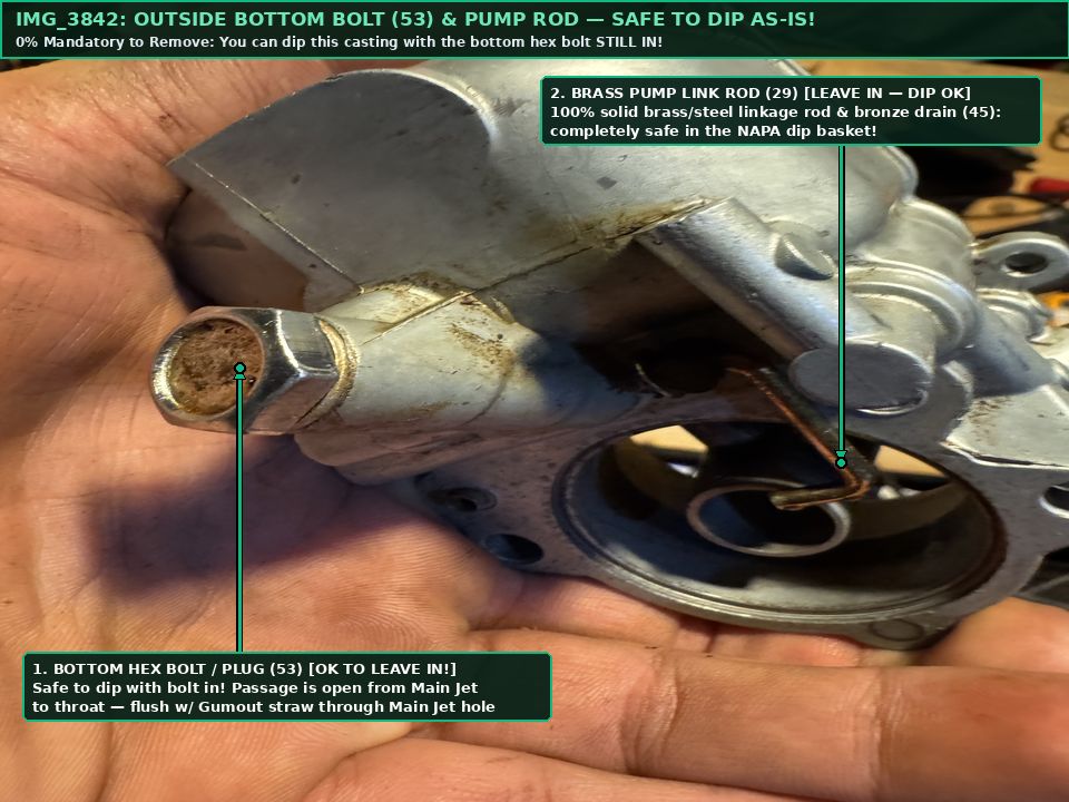
IMG_3842: Outside Bottom Hex Bolt (53) & Pump Rod — [OK TO LEAVE IN!]
1. Bottom Hex Bolt / Plug (53): Safe to dip with the bolt still threaded in! The passage behind it is open through Main Jet (40) and the main discharge nozzle. 2. Brass Pump Link Rod (29) & Bronze Drain (45): 100% metal—leave in place.
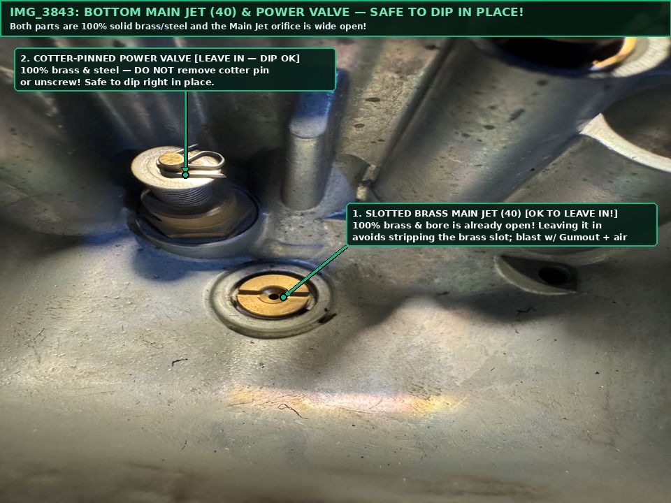
IMG_3843: Bottom Brass Main Jet (40) & Power Valve — [OK TO LEAVE IN!]
1. Slotted Brass Main Jet (40): 100% solid brass and its center orifice is wide open. Dipping in place prevents slot damage; blast center hole with Gumout + air after soaking. 2. Cotter-Pinned Power Valve: 100% brass/steel—never remove cotter pin.
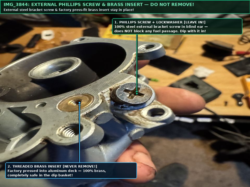
IMG_3844: External Phillips Screw & Brass Insert — [DO NOT REMOVE!]
1. Phillips Screw + Lockwasher: 100% steel external bracket screw in a blind outer ear—does not block any fuel circuit. Leave it in! 2. Threaded Brass Insert: Permanently pressed into the aluminum deck at the factory.
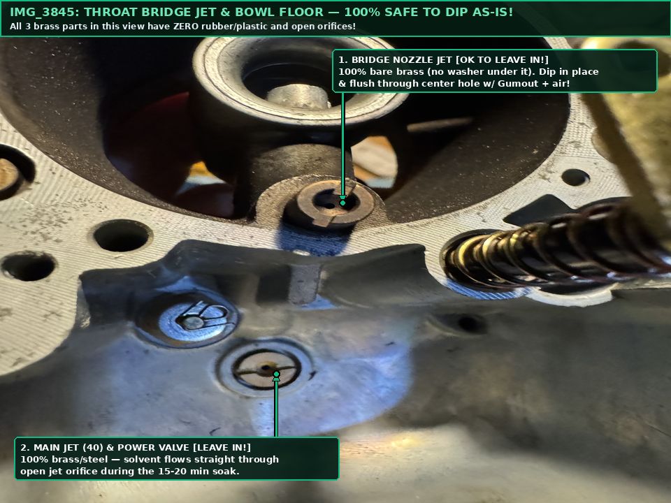
IMG_3845: Throat Bridge Nozzle Jet & Bowl Floor — [OK TO LEAVE IN!]
1. Bridge Nozzle Jet: 100% bare brass (no washer underneath). Leaving it threaded in avoids stressing the cast aluminum bridge arm; flush straight through its center hole with Gumout + air. 2. Main Jet (40) & Power Valve: Safe to dip in place.
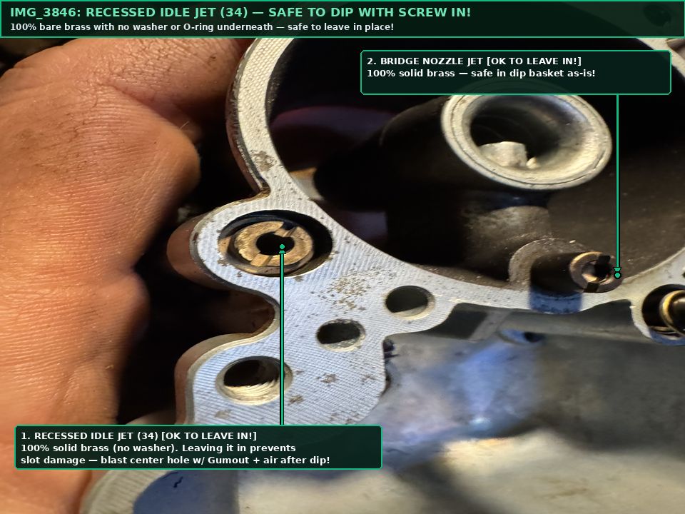
IMG_3846: Recessed Slotted Brass Idle Jet (34) — [OK TO LEAVE IN!]
1. Recessed Idle Jet (34): 100% solid brass with no washer or O-ring underneath. Dipping with it in protects the recessed screwdriver slot; backflush with Gumout + air through the center hole and bottom Idle Bushing (47) after soaking.
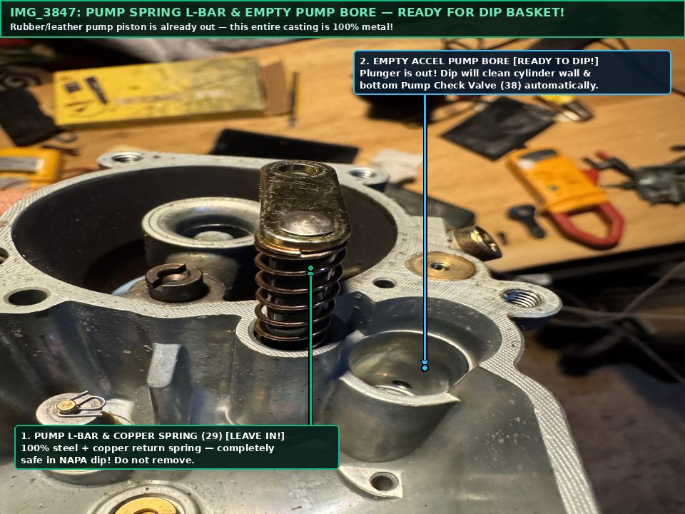
IMG_3847: Pump L-Bar Spring & Empty Pump Bore — [100% READY TO DIP!]
1. Pump L-Bar & Copper Spring (29): 100% steel and copper—leave attached. 2. Empty Accelerator Pump Bore: Since you already removed the plunger, the dip solvent flows directly into the bore and cleans Check Valve (38) at the base.
✅ TOP PIECE LIVE VERDICT (IMG_3854–IMG_3861): 0% MANDATORY TO REMOVE — DROP THIS ENTIRE TOP PIECE (AIR HORN 14) IN THE DIP BASKET RIGHT NOW!
You already removed the Top Hex Plug (15) with the White Nylon Filter Screen (17) (the empty threaded port is visible in IMG_3859), along with the Float (26), Float Pin (27), and Needle! Every single piece still attached in IMG_3854–IMG_3861 is 100% solid Aluminum, Brass, and Steel—you can drop the entire Top Piece straight into the NAPA dip basket as-is for 20–30 minutes:
IMG_3854,IMG_3855&IMG_3856— Wide-Slotted Brass Fuel Valve Seat (22): ✅ OK TO DIP IN PLACE! 100% solid brass (and its clamped vulcanized fiber washer will not melt in a 20–30 minute soak). If you choose to swap in the brand-new brass seat(22)+ red washer(23)from your kit afterward, the 20-minute dip dissolves old thread varnish so it unscrews easily after soaking!IMG_3855,IMG_3856&IMG_3860— Hex Brass Vacuum Power Piston + Steel Spring & Pressed Brass Bleed Tube: ✅ 100% LEAVE IN! Factory-staked solid brass and steel—after dipping and rinsing with Gumout, press the spring-loaded plunger up and down a few times with your finger to verify smooth travel.IMG_3857&IMG_3861— External Choke Linkage, Slotted Clamp Screws & Choke Shaft: ✅ 100% LEAVE IN! Solid steel/brass—do not disturb the choke plate alignment or risk losing those small screws. Put 1 drop of clean motor oil on the choke shaft pivots after blowing dry.IMG_3858&IMG_3859— 5/8" Hex Metal Fuel Line Barb & Empty Top Filter Port: ✅ 100% READY TO DIP! Solvent flushes straight through the metal hose barb, through the empty filter chamber, and out the center bore of Brass Seat(22).
🟢 Top Piece (Upper Air Horn 14) "Dip As-Is" Verification Atlas (IMG_3854–IMG_3861 — Click Any Photo to Zoom)
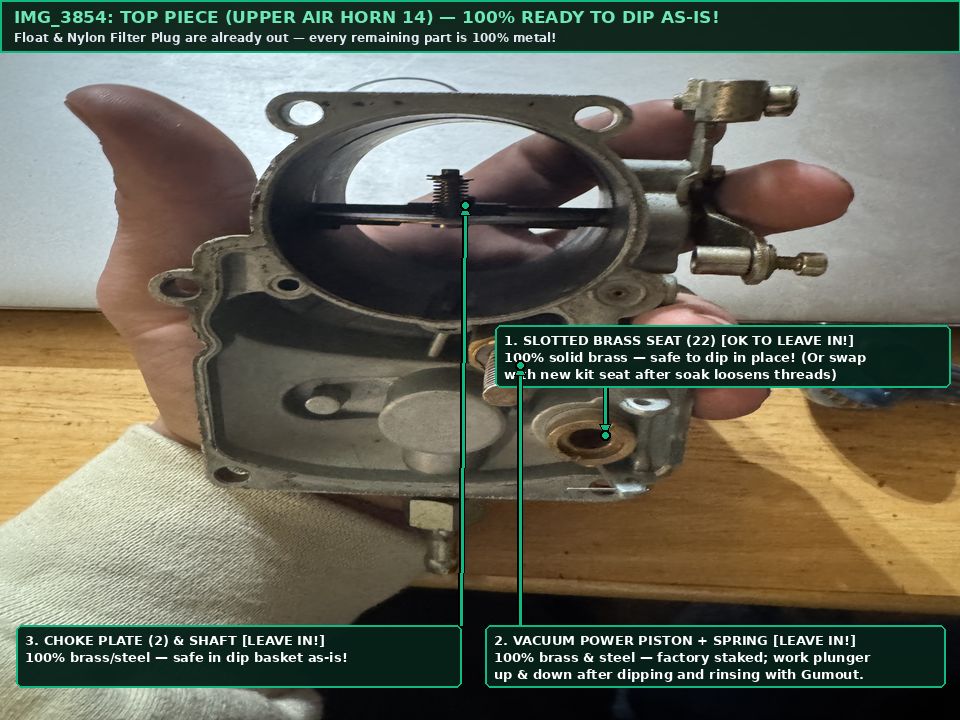
IMG_3854: Top Piece Underside Overview (14) — [100% READY TO DIP!]
1. Slotted Brass Seat (22): Safe to dip in place! 2. Vacuum Power Piston + Spring: 100% brass/steel—leave installed. 3. Choke Plate (2) & Poppet Spring: 100% metal—safe in the NAPA basket.
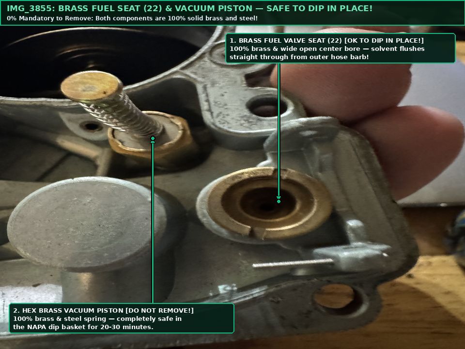
IMG_3855 / 3856: Brass Fuel Seat (22) & Vacuum Piston — [OK TO LEAVE IN!]
1. Brass Fuel Valve Seat (22): Wide-open center bore lets dip flush straight through from the outer fuel barb. 2. Hex Brass Vacuum Piston: Factory staked; do not remove.
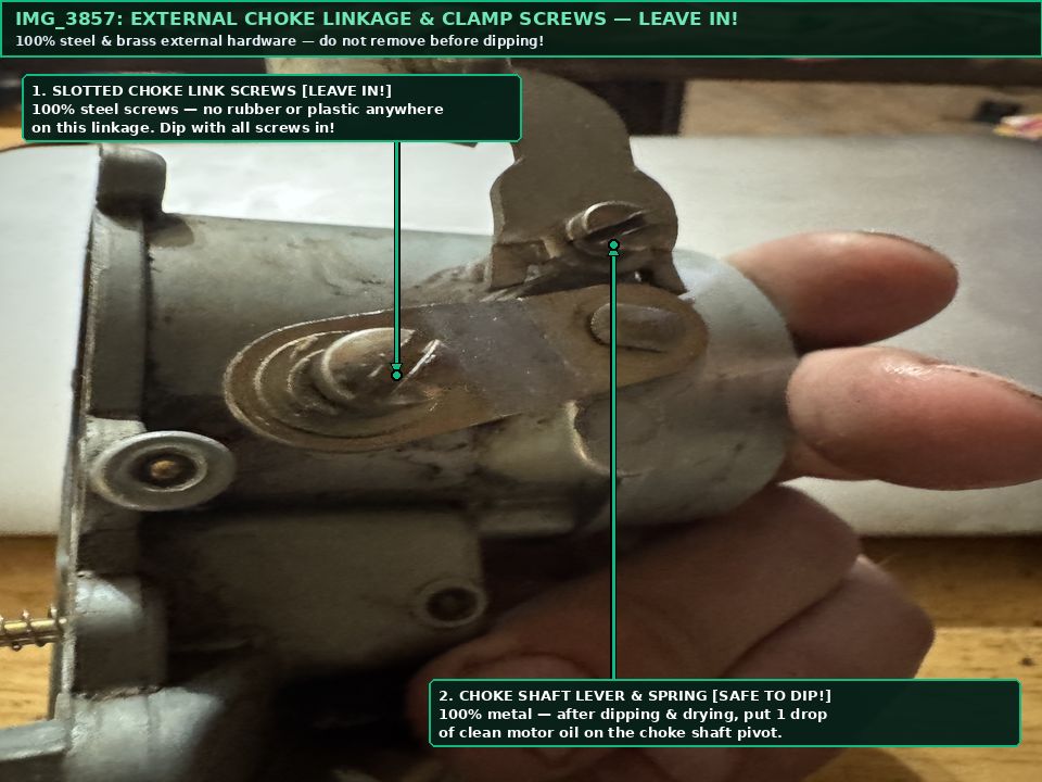
IMG_3857 / 3861: External Choke Linkage & Screws — [LEAVE IN!]
1 & 2. Slotted Choke Link Screws & Lever: 100% steel and brass with zero rubber or plastic. Leave all choke screws installed and add 1 drop of oil to the shaft pivots after drying.
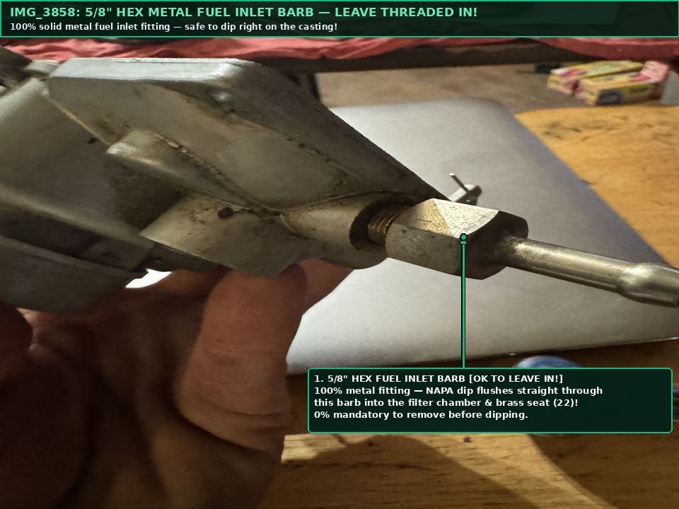
IMG_3858: 5/8" Hex Metal Fuel Inlet Barb — [OK TO LEAVE IN!]
1. 5/8" Hex Fuel Inlet Barb: 100% solid metal fitting—NAPA dip cleans straight through the barb and into the filter bowl cavity.
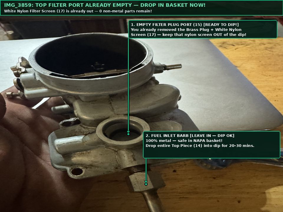
IMG_3859: Top Filter Port Already Empty — [DROP IN BASKET NOW!]
1. Empty Filter Plug Port (15): You already removed the Brass Plug + White Nylon Filter Screen (17)—so zero non-metal parts remain on this casting!
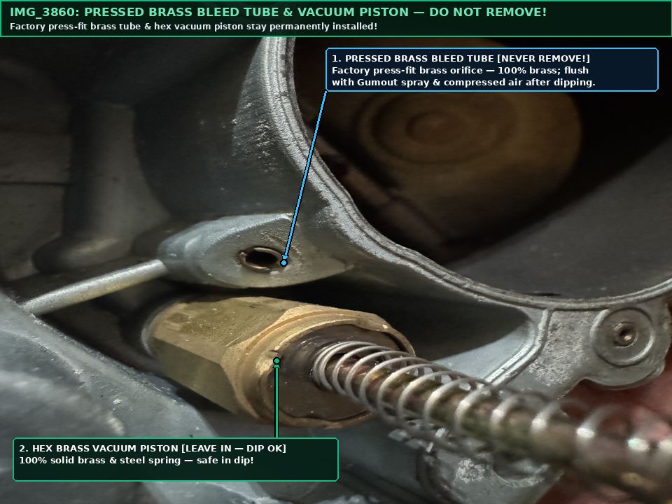
IMG_3860: Pressed Brass Bleed Tube & Vacuum Piston — [DO NOT REMOVE!]
1. Pressed Brass Bleed Tube: Factory press-fit orifice—never pry; flush with Gumout + compressed air after soaking. 2. Hex Brass Vacuum Piston: Safe in dip!
📄 KIT INSTRUCTION SHEET DECODED (IMG_3827–IMG_3831): USE FRONT SIDE (FORM NO. 08050-397 ZENITH 28–228) & IGNORE BACK SIDE (1973–74 OPEL MANTA 2-BARREL)!
Your photos of the folded instruction sheet from the K4042 / 31-546 rebuild kit solve every remaining question about the extra parts in your kit—and reveal an important paper-saving print quirk on the reverse side:
- 1. ⛔ IGNORE THE BACK SIDE (
IMG_3830&IMG_3831— 1973–1974 Opel 1900 & Manta / GT 2-Barrel): Techlit Co. printed an unrelated 1973–1974 Opel 1900 / Manta / GT 2-barrel passenger-car adjustment sheet (FIG. 1–FIG. 5,Secondary Throttle Valve,3200 RPM Fast Idle Cam) on the back side to save paper. None of the back side applies to your single-barrel Ford / Gehl Zenith 228 carburetor! - 2. ✅ FRONT SIDE (
IMG_3827&IMG_3829—Form No. 08050-397, Zenith Series 28–228) Confirms Which Idle Needle to Use: Under Special Instructions, the sheet shows why your kit came with multiple brass idle needles:28 SERIES IDLE NEEDLE (BOWL COVER)— DO NOT USE: Short body with a blunt/stepped tip (threads into the upper cover on Series 28 carbs; clockwise = richer).228 SERIES IDLE NEEDLE (THROTTLE BODY #34)— USE THIS ONE: Longer threaded body with a long fine tapered point that threads into your Cast-Iron Throttle Body (sheet callout#34, Ford callout#20). On your 228 Series, clockwise = LEANER. Turn in lightly until seated, then back out1 turn(1 to 1-1/2 turns).
- 3. ✅ Exact Float Level Match (
1-31/64"=1.484 in. / 37.7 mm): The bottom-right diagram onForm No. 08050-397specifies1-31/64"(= 1.484375 in.) measured from the machined surface of the inverted bowl cover (without gasket) to the top center of the float—matching the Ford KSG-416 factory manual (1.484 in.) to the thousandth of an inch! - 4. ✅ Accelerator Pump Plunger 3-Groove Diagram (
#20on Sheet /#29in Ford Manual): Shows the 3 stroke grooves on your new pump plunger stem: Top Groove =HALF STROKE(Ford calls it1/4 stroke), Middle Groove =THREE QUARTERS STROKE, Bottom Groove =FULL STROKE. Install the hairpin retainer clip in the top groove (matching original disassembly). - 5. ✅ Exploded View Cross-Reference (
#5AScreen Filter Vacuum Piston Note): Notice#5A FILTER - SCREEN TYPEon the top-left ofIMG_3829—that is your exact white nylon mesh filter screen under Top Hex Plug#3! Also note the sheet's Cleaning note onVacuum Piston Assy. (#11)(because a thin fiber gasket#12sits under its hex shoulder): after your 20-minute dip, flush the Vacuum Piston thoroughly with Gumout, blow dry with compressed air, and press the brass plunger up and down a few times to verify crisp spring return.
📐 Annotated Kit Instruction Sheet Atlas (Form No. 08050-397 Front vs. Opel Back — IMG_3827–IMG_3831)
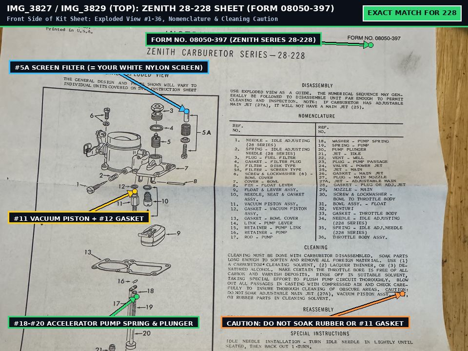
IMG_3827 / 3829 (Top): Zenith 28–228 Sheet (Form 08050-397) — [EXACT MATCH]
1. Form No. 08050-397: Official Zenith Series 28–228 instruction sheet. 2. #5A Screen Filter: Confirms your white nylon mesh screen variant. 3. #11 Vacuum Piston + #12 Gasket: Flush and exercise plunger after cleaning.
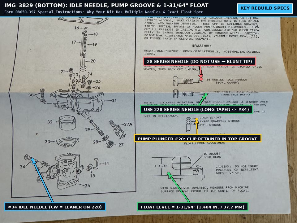
IMG_3829 (Bottom): 228 Idle Needle, Pump Groove & 1-31/64" Float — [KEY SPECS]
1. Use 228 Series Idle Needle (#34): Long fine taper for Cast-Iron Throttle Body (clockwise = leaner; back out 1 turn). 2. Pump Plunger (#20): Clip retainer in top groove. 3. Float Level: 1-31/64" (1.484 in. / 37.7 mm) inverted.
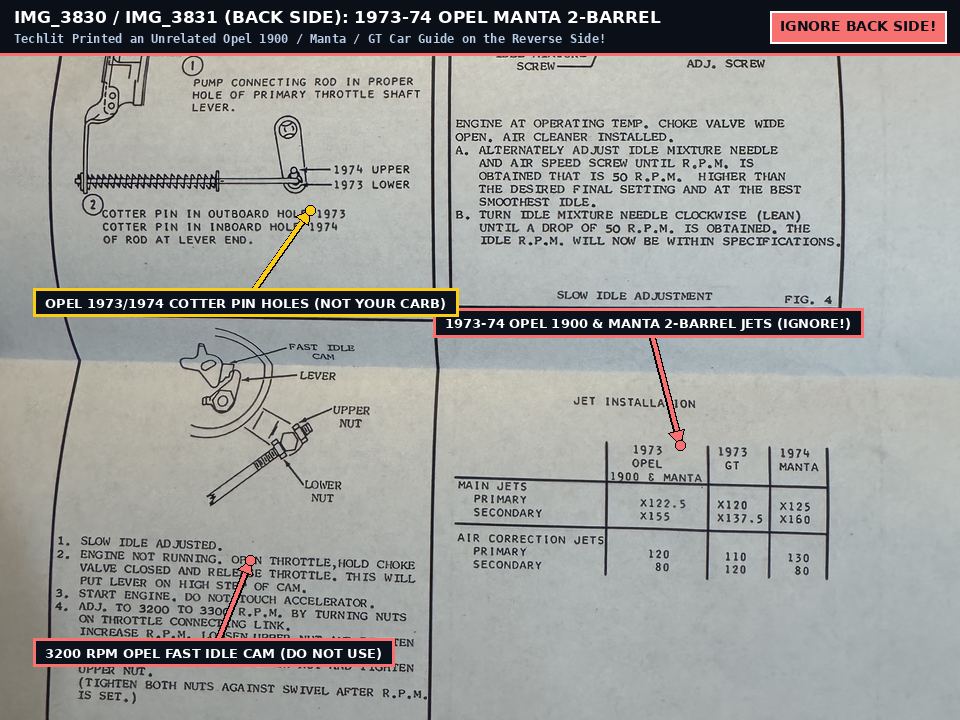
IMG_3830 / 3831 (Back Side): 1973–74 Opel Manta 2-Barrel — [IGNORE BACK SIDE!]
1. Unrelated Reverse Print: Techlit printed a 1973–1974 Opel 1900 & Manta 2-barrel car carburetor sheet on the back side. Disregard all figures (FIG. 1–5) and jet tables on this reverse side!
🔧 Final Pre-Dip Removal Checklist: Top Piece (Air Horn 14) & Middle Piece (Fuel Bowl 46)
Your conical Primary Venturi (50) already shined up in the NAPA basket! Before dropping the Top Piece (14) and Middle Piece (46) into the basket, unscrew only these 5 threaded brass parts visible in your last bench photos (IMG_3812–IMG_3825):
- Top Piece (
Upper Air Horn 14— seePlate A): Only 1 item needs to come out: unscrew#1 in Plate A— Wide-Slotted Brass Fuel Valve Seat (22) and remove the red fiber washer (23) trapped underneath it (so the fiber washer doesn't turn to mush; your kit has a brand-new seat + red washer). Leave the Vacuum Power Piston (#4), 5/8" Fuel Inlet (#2), and Choke Plate attached—100% metal and safe to dip! Keep Top Hex Plug (15) with White Nylon Screen (17) (Plate E) OUT of the bucket. - Middle Piece (
Aluminum Fuel Bowl 46— seePlates B, C & G): Unscrew 4 brass parts and drop the bare brass jets/plugs in the basket (setting the 2 fiber washers aside dry):#1 in Plate G (IMG_3814)— Outside Bottom Brass Hex Plug (53) + Fiber Washer (52): Flip the middle piece over, unscrew the large brass hex plug on the angled bottom snout with a wrench, and remove its fiber washer(52)so dip cleans the main passage behind it.#1 in Plate B (IMG_3822)— Bottom Main Metering Jet (40) + Small Fiber Washer (41): Unscrew from the bottom floor of the fuel bowl and lift out the small fiber washer(41)underneath it.#6 in Plate B / #4 in Plate C— Recessed Idle Jet (34): Unscrew from the top rim well beside the throat (no washer).#5 in Plate B / #3 in Plate C— Booster Bridge Nozzle Jet: Unscrew from the horizontal bridge arm inside the throat (no washer).
#2 in Plate B), Pump Guide Rod + Copper Spring + L-Bar (#5 in Plate C), Bronze Drain Filter (#2 in Plate G), Smooth Brass Insert (#4 in Plate B), and Cast Center Booster Ring (#2 in Plate C) untouched on the casting!
🪝 Hanging Wire Rules in the NAPA Dip Bucket: Stripped Solid Copper Wire vs. Bare Steel Wire
The NAPA 1-Gallon Carburetor Parts Cleaner includes a perforated steel strainer basket, or you can suspend castings on wire hooks:
- #1 Winner for Aluminum Castings (
14, 46, 50): Stripped Bare Solid Copper Wire (12–14 AWG): Bare copper (~35 HBBrinell / Mohs3.0) is softer than die-cast aluminum (~70 HB) and brass threads (~60 HB). Looping stripped bare copper wire through outer perimeter bolt holes(18)cannot scratch or burr machined gasket decks. MANDATORY: Strip 100% of plastic/PVC insulation off electrical copper wire first (solvent melts vinyl insulation into sticky goo), and limit soak to20–30 minutes(never leave copper touching aluminum overnight). - When Bare Steel Mechanics / Bailing Wire is OK: Uncoated steel wire (
~120+ HB) is stiffer and great for upper bucket-rim J-hooks or hanging the heavy Cast-Iron Throttle Body (57) through its5/16"flange bolt ears—just never drag steel wire across soft aluminum sealing surfaces or brass threads. - ⛔ Ford Page 3-04 Orifice Protection Law: NEVER thread copper OR steel wire through the calibrated center hole of any brass jet (
40, 34, Bridge Jet)! Set loose brass jets directly inside the NAPA perforated steel basket (or wrap soft bare copper wire around the outside waist of the jet body only).
🎯 Labeled Arrow & Callout Identifier Plates (Plates A–G — Click Any Plate to Zoom Full-Screen)
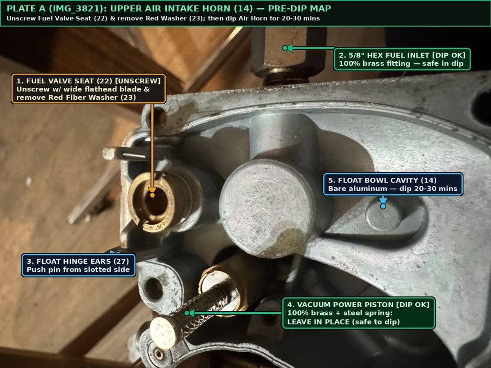
Plate A (IMG_3821): Top Piece — Upper Air Intake Horn (14) Pre-Dip Map
1. Fuel Valve Seat (22) [UNSCREW]: Use a wide flat blade to unscrew the slotted brass seat and remove red fiber washer (23) before dipping. 2. 5/8" Hex Fuel Inlet [DIP OK]: Permanent fitting. 3. Float Hinge Ears (27): Slotted ear vs blind ear. 4. Vacuum Power Piston [DIP OK]: Factory staked in bore—soak in place and work plunger up/down afterward.
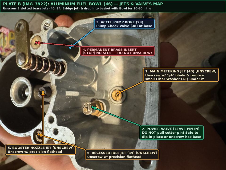
Plate B (IMG_3822): Middle Piece Inside — Fuel Bowl (46) Jets & Valves Map
1. Main Metering Jet (40) [UNSCREW]: Unscrew from bottom inclined boss & remove fiber washer (41). 2. Power Valve [LEAVE PIN IN]: Keep tiny cotter pin in place; dip assembly intact. 3. Accel Pump Bore (29): Clean cylinder wall & bottom intake port. 4. Permanent Brass Insert [STOP]: Press-fit bushing—never pry. 5 & 6. Booster Nozzle & Idle Jet (34) [UNSCREW]: Unscrew with hollow-ground cabinet driver.
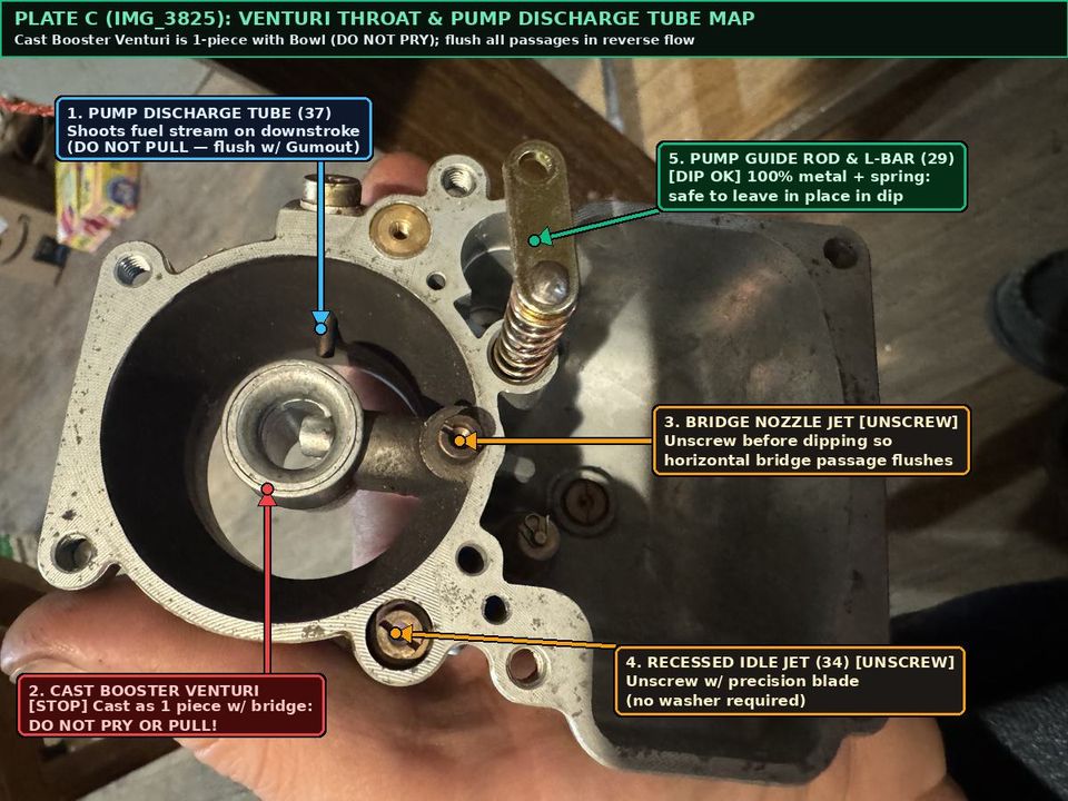
Plate C (IMG_3825): Middle Piece Throat — Venturi & Top Deck Map
1. Pump Discharge Tube (37): Verify crisp stream exits this brass tube during bench pump test. 2. Cast Booster Venturi [STOP]: Cast 1-piece with aluminum bowl—DO NOT PRY. 3 & 4. Bridge Nozzle & Idle Jet (34) [UNSCREW]: Unscrew before dipping. 5. Pump Guide Rod & L-Bar (29) [DIP OK]: All metal/brass/copper—safe to soak right on the casting.
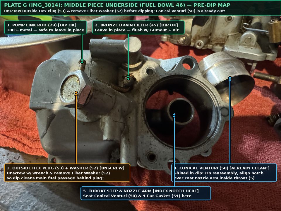
Plate G (IMG_3814): Middle Piece Underside — Outside Hex Plug (53) & Washer (52) Map
1. Outside Bottom Hex Plug (53) + Fiber Washer (52) [UNSCREW]: Unscrew with a wrench and remove Fiber Washer (52) so solvent flushes straight up the main passage! 2. Sintered Bronze Drain Filter (45) [DIP OK]: Leave installed; flush with Gumout + air. 3. Pump Link Rod (29) [DIP OK]. 4 & 5. Conical Venturi (50) & Throat Step: Already shined in dip—index rectangular notch over nozzle arm on reassembly.
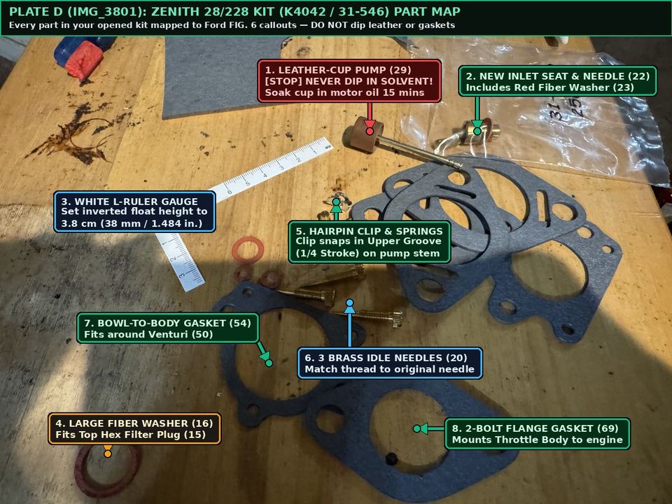
Plate D (IMG_3801): Opened Zenith 28/228 Kit (K4042 / 31-546) Map
1. Brown Leather-Cup Pump (29) [STOP]: Soak leather skirt in motor oil 15 min (never solvent). 2. New Inlet Seat & Needle (22) + Red Washer (23). 3. White L-Ruler Gauge: Set inverted float height to 3.8 cm (1.484 in.). 4. Fiber Washer (16). 5. Hairpin Clip & Springs: Upper groove = 1/4 stroke. 6. Brass Idle Needles (20). 7. Throttle Gasket (54). 8. Flange Gasket (69).
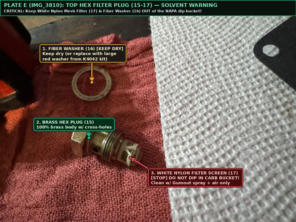
Plate E (IMG_3810): Top Hex Filter Plug (15–17) — Solvent Warning
1. Fiber Washer (16) [KEEP DRY]: Match against new red fiber washer in kit. 2. Brass Hex Plug (15). 3. White Nylon Filter Screen (17) [STOP]: Your carburetor uses a molded white nylon mesh screen attached to the nose of Plug (15). DO NOT submerge in the NAPA dip bucket—clean with a brief Gumout spray and low-pressure air only.
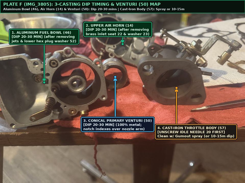
Plate F (IMG_3805): 3-Casting Dip Timing & Conical Venturi (50) Map
1. Aluminum Fuel Bowl (46): Dip 20–30 min after unscrewing brass jets & outside plug (53). 2. Upper Air Horn (14): Dip 20–30 min after unscrewing Seat (22). 3. Conical Primary Venturi (50): Already dipped & shined! Index rectangular bottom notch over main nozzle boss on reassembly. 4. Cast-Iron Throttle Body (57): Unscrew Idle Needle (20) first; clean with Gumout spray or 10–15 min max dip, then oil shaft pivots.
🧰 Opened Kit Identification: Bag Code 31-546 / 25G2 = Zenith 28 / 228 Master Kit (K4042 / Gehl 073702)
Your photos IMG_3801–IMG_3804 and IMG_3807 confirm the exact replacement components staged on your bench:
- Complete New Brass Accelerating Pump Plunger (29) with Brown Leather Cup (
IMG_3803): Directly replaces the old plunger whose nitrile rubber ring broke in half inIMG_3241! Condition the brown leather skirt in clean motor oil for 15–20 minutes, compress the lip gently with your fingers while guiding it down the fuel bowl pump cylinder, and lock the new stamped-steel hairpin retainer clip (IMG_3803) into the upper groove (1/4 stroke) of the pump rod. - 6-Screw Upper Bowl Gasket (28) on Paper Towel (
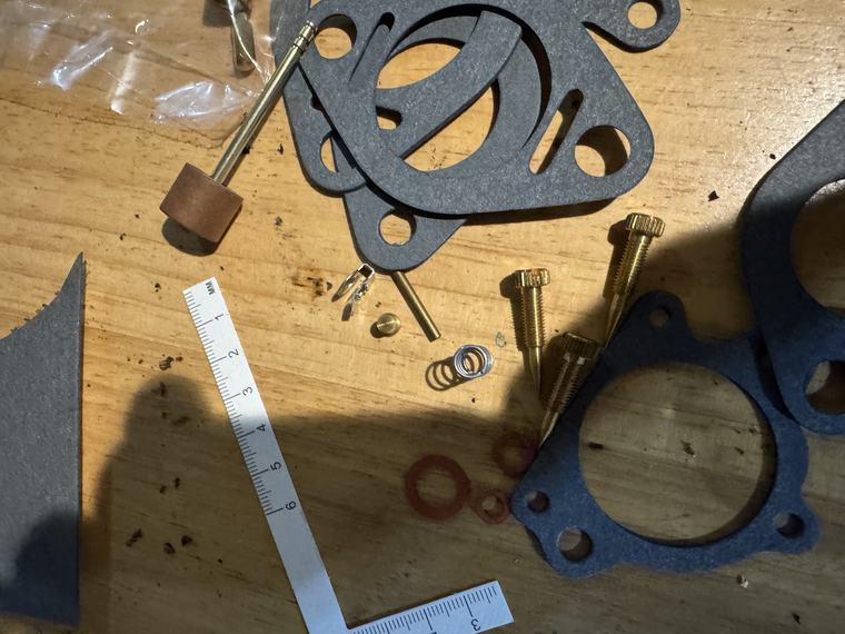
IMG_3807): Exact die-cut match for your Zenith 228 6-screw fuel bowl perimeter—install dry after calibrating the float level. - White L-Shaped Float Ruler Gauge (
IMG_3801): Place against the inverted machined face of Air Horn(14)(with Gasket28removed) to verify1.484 in. (37.7 mm / 3.8 cm)to the top of the float pontoons.
🔩 Cast-Iron Throttle Body (57) & Venturi (50) Bench Notes (IMG_3806–IMG_3809)
Before dipping and reassembling the lower half of the carburetor, note these three bench checkpoints from your macro photos:
- Count Idle Mixture Needle (20) Turns Before Removal (
IMG_3809): Turn the knurled brass idle needle gently clockwise until lightly seated and record the exact turn count (factory baseline is1 to 1-1/2 turns out), then unscrew it and remove tension spring(21). Note that your kit includes 3 brass idle needles to cover multiple Zenith 28/228 sub-models—compare the taper point against your original needle before swapping. - Throttle Bore Gasket (54) Orientation (
IMG_3801,IMG_3808): Ensure the idle transfer channel hole at the mating flange is completely unobstructed when mating Cast-Iron Body(57)to Aluminum Bowl(46). - Conical Primary Venturi (50) Indexing Notch (
IMG_3805,IMG_3806): When dropping the cleaned conical venturi sleeve back into the throat of Bowl(46), align its rectangular bottom cutout squarely over the angled discharge arm so the sleeve drops flush.
📸 Additional Macro Bench Inspection Plates (IMG_3802–IMG_3826)
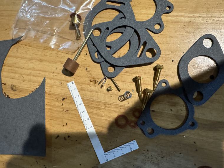
28. Kit Bag Code 31-546 / 25G2 & Red Fiber Washers (IMG_3802)
Close-up of the inner hardware bag stamped 31-546 / 25G2 containing the 4 red vulcanized fiber sealing washers (16, 23, 41, 52), new slotted brass Fuel Valve Seat (22), and Viton-tipped inlet needle.
29. New Leather-Cup Pump (29) & Hairpin Clip (IMG_3803)
The new brass-stem Accelerating Pump Plunger (29) with its brown leather cup skirt beside the stamped steel hairpin retainer clip and coil springs. Soak the leather cup in clean motor oil for 15–20 minutes before installation.
30. Fuel Bowl (46) With Primary Venturi (50) Extracted (IMG_3806)
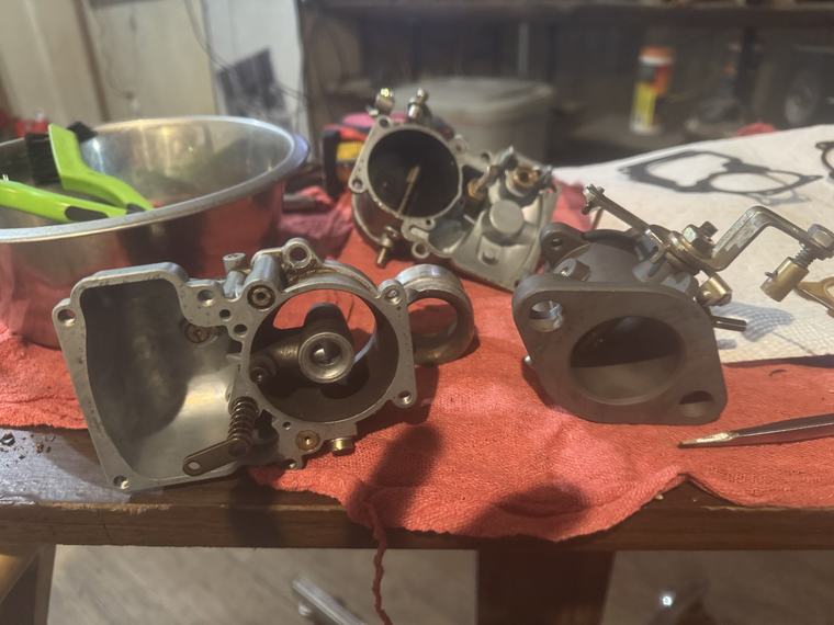
With the removable conical Primary Venturi (50) lifted out of the lower throat, the internal cast booster ring and main discharge passage inside Fuel Bowl (46) are wide open for solvent cleaning.
31. 6-Screw Bowl Gasket (28) & Flange Gasket (69) (IMG_3807)
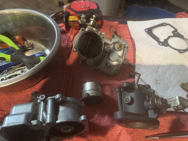
Your new 6-screw Bowl-to-Air-Horn Gasket (28) and 2-bolt Manifold Flange Gasket (69) staged dry on a white paper towel. Keep all paper/fiber gaskets completely dry and out of the dip bucket.
32. Cast-Iron Throttle Body (57) & Brass Plate (56) (IMG_3808)
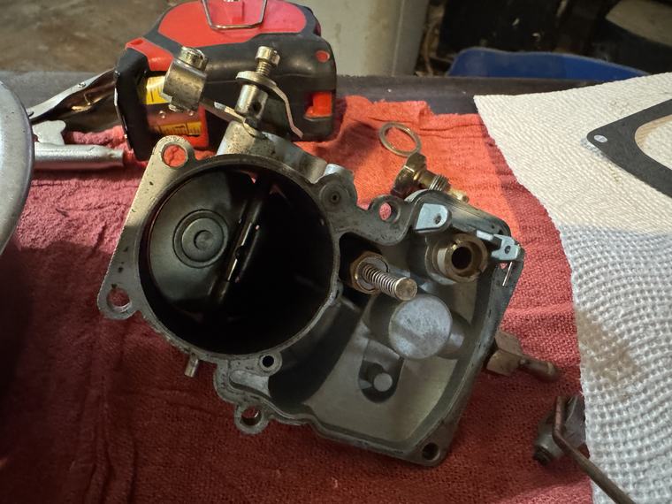
Top-down view of the separated Cast-Iron Throttle Body (57) showing the staked screws (55) on Beveled Brass Throttle Plate (56) and the vertical idle channel drilling in the flange face.
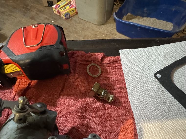
33. Idle Adjusting Needle (20) & Throttle Stop (66) (IMG_3809)
Side profile of Cast-Iron Throttle Body (57): turn knurled brass Idle Needle (20) gently clockwise to record its current turn count before unscrewing it and flushing the idle transfer port with Gumout.
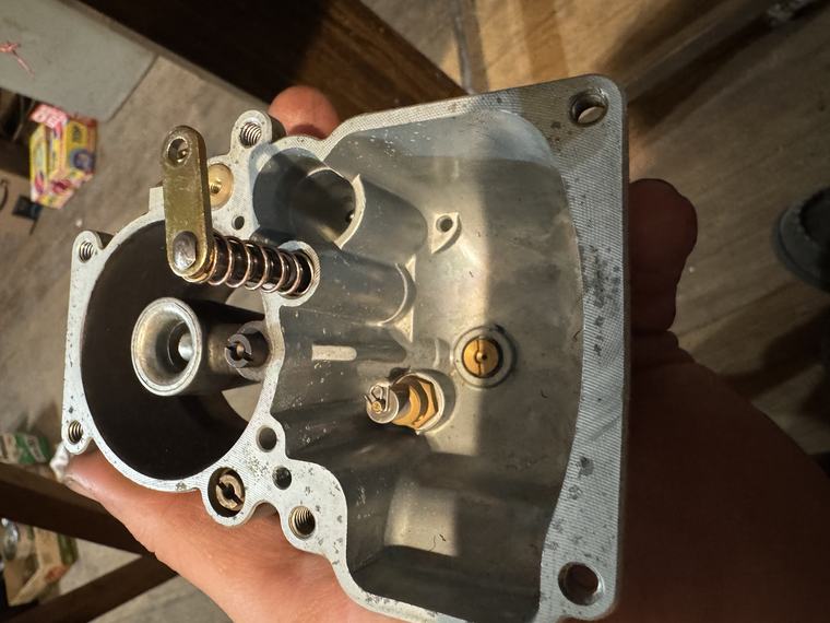
34. Macro Bowl Verification: Main Jet (40) & Power Valve (IMG_3823)
Alternate macro angle into Fuel Bowl (46) highlighting the slotted Main Metering Jet (40) at the bottom of the inclined boss and the cotter-pinned brass Power Valve assembly beside the pump cylinder.
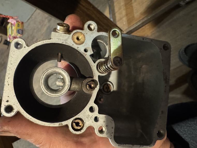
35. Macro Throat Verification: Discharge Tube (37) (IMG_3826)
High-angle macro view of the brass Accelerating Pump Discharge Tube (37) protruding into the air horn wall right above the integral cast primary booster ring.
Phase 3: Solvent Cleaning, Circuit Backflushing & Bench Pump Check (Pages 3-04 & 3-05)
3.1 Brass Jet & Aluminum Casting 20–30 Minute Dip Basket Soak
Place the bare aluminum castings (Air Horn 14, Fuel Bowl 46, Primary Venturi 50) and all unscrewed brass jets—Idle Jet (34), Accelerating / Bridge Nozzle Jet (37/39), Main Jet (40), Main Discharge Nozzle (51), Fuel Valve Seat (22), and Idle Needle (20) (with all red/grey fiber washers removed)—into the NAPA Carburetor Parts Cleaner dipping basket for 20 to 30 minutes (45 minutes max). ⚠️ NEVER put the white nylon Fuel Filter Screen (17) (IMG_3810) or the brown leather-cup Pump Plunger (29) (IMG_3803) into the dip bucket! Clean the white nylon filter screen with a brief Gumout aerosol spray + low-pressure air only, and soak the new leather pump cup in clean motor oil for 15–20 minutes. Rinse dipped metal parts with Gumout Jet Spray and blow dry in reverse flow with compressed air. Inspect every orifice against a bright light—never poke metal wire through the calibrated brass bores.
3.2 Idle Circuit & Transfer Port Backflushing
Locate the drilled Idle Discharge & Off-Idle Transfer Ports in the wall of Cast-Iron Throttle Body (57) right at the edge of Brass Throttle Plate (56) (shown in carb-flange.jpeg). Inject Gumout Jet Spray through the Idle Adjusting Needle (20) port and through the upper Idle Channel Bushing (47). Verification: Solvent and air must exit freely from both throttle-bore transfer ports and the idle jet seat.
3.3 Main Metering, Well Vent & Bowl Drain Filter Verification
Flush solvent into the Main Jet (40) boss and Well Vent (39) passage inside Fuel Bowl (46). Verify an unrestricted stream exits the angled Main Discharge Jet (51) inside Primary Venturi (50). Flush the sintered bronze Bowl Drain Plug (45) at the underside of the fuel bowl so atmospheric bowl drain/venting is clean.
3.4 Mandatory Bench Accelerating Pump Action Test (Ford Page 3-05)
Before installing the air horn, reinstall the Fuel Bowl jets and Accelerating Pump Piston (29), then perform the official Ford Page 3-05 "CHECK PUMP ACTION" test on the bench:
- a. Fill Bowl: Pour clean gasoline or mineral spirits (~1/2" deep) into Fuel Bowl (46).
- b. Test Air Vent Check Valve (30): Push Pump Piston (29) briskly downward and verify no fuel leaks upward out of Air Vent Check Valve (30).
- c. Test Pump Check Valve (38): Repeat the downstroke and verify Pump Check Valve (38) seals completely (fuel must not bubble backward into the float bowl through the intake channel at the bottom of the pump cylinder).
- d. Verify Accelerating Jet (37) Stream: Confirm a sharp, solid stream shoots out of Accelerating Jet (37) on every downstroke.
Phase 4: Precision Reassembly & 1.484" (1-1/2") Float Calibration (Pages 3-05 & 3-06)
Phase 4.1: Install Fuel Bowl Jets, Index Venturi (50) & Metal-Ringed Gasket (54)
Thread Idle Jet (34), Accelerating Jet (37), and Well Vent Jet (39) (no gaskets required) into the top of Fuel Bowl (46). Install Main Jet (40) with Fiber Washer (41) inside the bowl bottom, and install Main Discharge Nozzle (51) and Main Passage Plug (53) with Fiber Washer (52). Seat Accelerating Pump Piston (29) with its hairpin clip in the original groove (upper groove = 1/4 stroke; lower groove = 1/2 stroke). Lower Primary Venturi (50) into the fuel bowl: CRITICAL (Ford p. 3-06 Step 1): The indexing notch in Venturi (50) MUST fit squarely over the main discharge arm of the fuel bowl. Place Gasket (54) around the venturi: CRITICAL (Ford p. 3-06 Step 2): One hole in Gasket (54) is reinforced with a metal ring—the protruding Idle Channel Bushing (47) must pass through this metal ring.
Phase 4.2: Mount Pump Lever (58), Set Bench Screws (20, 66) & Install Float (26)
Assemble Cast-Iron Throttle Body (57) to Fuel Bowl (46) with the two screws (48) and lockwashers. Install Pump Lever (58), Lockwasher (61), and Nut (60) onto Throttle Shaft (67): CRITICAL (Ford p. 3-06 Step 3): Mount Pump Lever (58) so the pump link hole sits directly under Pump Rod (29) and the lever points UPWARD when the throttle is closed. Thread Idle Adjusting Needle (20) & Spring (21) in until lightly seated, then back out 1 to 1-1/2 turns. Hold the throttle lever closed, turn Throttle Stop Screw (66) IN just to the point of contact with the stop, then turn IN 1-1/2 additional turns (Ford p. 3-06 Step 7). In Air Intake Body (14), install Fuel Valve Seat (22) + Fiber Washer (23), drop in the Fuel Valve Needle, position Float (26), and press Float Axle (27) into center position from the side opposite the slot (Ford p. 3-05 Step 6).
Phase 4.3: Calibrate Float Level — Factory Spec 1.484 in. (37.7 mm) / 1-1/2 in. (38.1 mm)
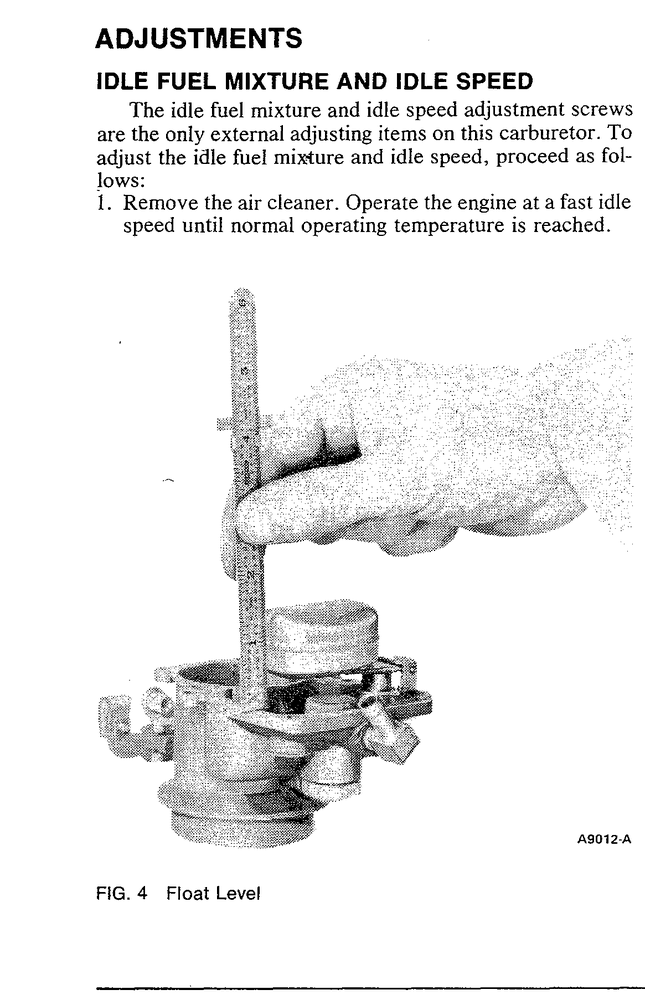
Invert Air Intake Body (14) with Gasket (28) REMOVED so only the weight of Float (26) rests on the fuel valve needle. Measure vertically from the machined gasket surface of Air Intake Body (14) to the top center of the float pontoons (see FIG. 4 at right). Factory Assembly Dimension (Ford p. 3-05 Step 7): 1.484 in. (37.7 mm) — Specification Range (Ford p. 3-03 & p. 8-04): 1-1/2 in. (38.1 mm) ± 1/32". (Never use the 1-5/32" / 29.4 mm updraft spec—that overfills the bowl by 8.3 mm!) If adjustment is needed, use long-nose pliers to bend the float lever close to the float body without pressing the needle into its seat.
Phase 4.4: Mate Air Horn (14) to Bowl (46) & Install Filter Element (17)
Position Bowl-to-Intake Gasket (28) on Fuel Bowl (46). Lower Air Intake Body (14) straight down so Float (26) enters the chamber cleanly. Install the six perimeter screws (18) and lockwashers, tightening them evenly in an alternating cross pattern (25–30 in-lbs). Insert cylindrical Fuel Filter Element (17) into the top bore, place Fiber Washer (16) on Hex Filter Plug (15), and thread Plug (15) securely into the cover.
Phase 5: Fuel Pressure Check & Gehl SL4510 Governor Synchronization
Phase 5.1: Fuel Pump Pressure Check & Gehl 1/32" WOT Linkage Sync (Engine OFF)
Before starting, verify fuel delivery pressure at the carburetor inlet is 3.5 to 5.0 PSI (24.5 to 34.3 kN/m²) (Ford p. 3-02 FIG. 2). Mount the carburetor onto intake manifold 781F-9425-ACA with a fresh Flange Gasket (69). Per Gehl SL4510 Service Manual 903931 Page 92 (Fig. 12-13 & 12-14):
- Eliminate Bailing Wire: Connect the governor control rod (Gehl P/N
074173/064102) and10-32ball joints (054885) between the governor arm and Carburetor Throttle Lever (64). - Set the 1/32" WOT Gap: Push the operator hand throttle control all the way forward to the FAST (Wide-Open) position. Adjust the governor-to-carburetor rod length so there is an exact
1/32 inch (0.8 mm)gap between the carburetor throttle lever and its Wide-Open Throttle (WOT) stop casting (preventing linkage over-stress while achieving full governor travel). - Verify Frictionless Sweep: Release the linkage and confirm the throttle snaps smoothly between closed and WOT without binding on the choke cable or manifold casting.
Phase 5.2: Zenith Idle Mixture Midpoint Tuning (Ford Page 3-03 & Gehl Page 92)
Start the engine, disengage all hydraulic/auxiliary loads, open the choke completely, and bring the KSG-416 engine to normal operating temperature:
- Base Mixture Tune (700–850 RPM): Per Ford Page 3-03, set base idle speed via Throttle Stop Screw (66) to
700 RPM(making sure the throttle linkage does not hold the stop screw off its seat). - Bracket Lean & Rich Drop-Off: Turn Idle Adjusting Needle (20) IN (clockwise) until engine speed begins to drop from a lean mixture. Next, turn Needle (20) OUT (counterclockwise) through the smooth zone until RPM drops from a rich, heavy mixture. Set Needle (20) halfway between those two points for maximum manifold vacuum and smoothness (Ford p. 3-03 Step 5).
- Set Gehl Skid-Steer Operating RPMs: Per Gehl Service Manual 903931 Page 92, set final installed Low Idle to
~1000 RPM(Ford standalone range700–850 RPM) and verify maximum governed no-load High Idle is~3000 RPMvia the governor high-speed stop screw.
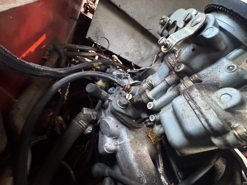
Phase 5.3: Governor Surge Screw Calibration (+25 RPM Max Rule — Gehl Page 92)
If the engine hunts or surges at wide-open no-load RPM after the idle mixture and linkage are properly set, calibrate the governor surge (bumper) screw per Gehl 903931 Page 92:
- Loosen Locknut & Advance Clockwise: With the hand throttle at full FAST (~3000 RPM no-load), slowly turn the governor surge screw clockwise (IN) just until the surging stops.
- Enforce the +25 RPM Limit: Gehl Page 92 specifies that turning the surge screw clockwise must never increase no-load engine speed by more than
~25 RPM. Advancing it further locks out the governor flyweights and causes dangerous overspeeding when bucket/hydraulic load is released. Lock the jam nut and test rapid bucket-curl load transitions.
