Electrical system
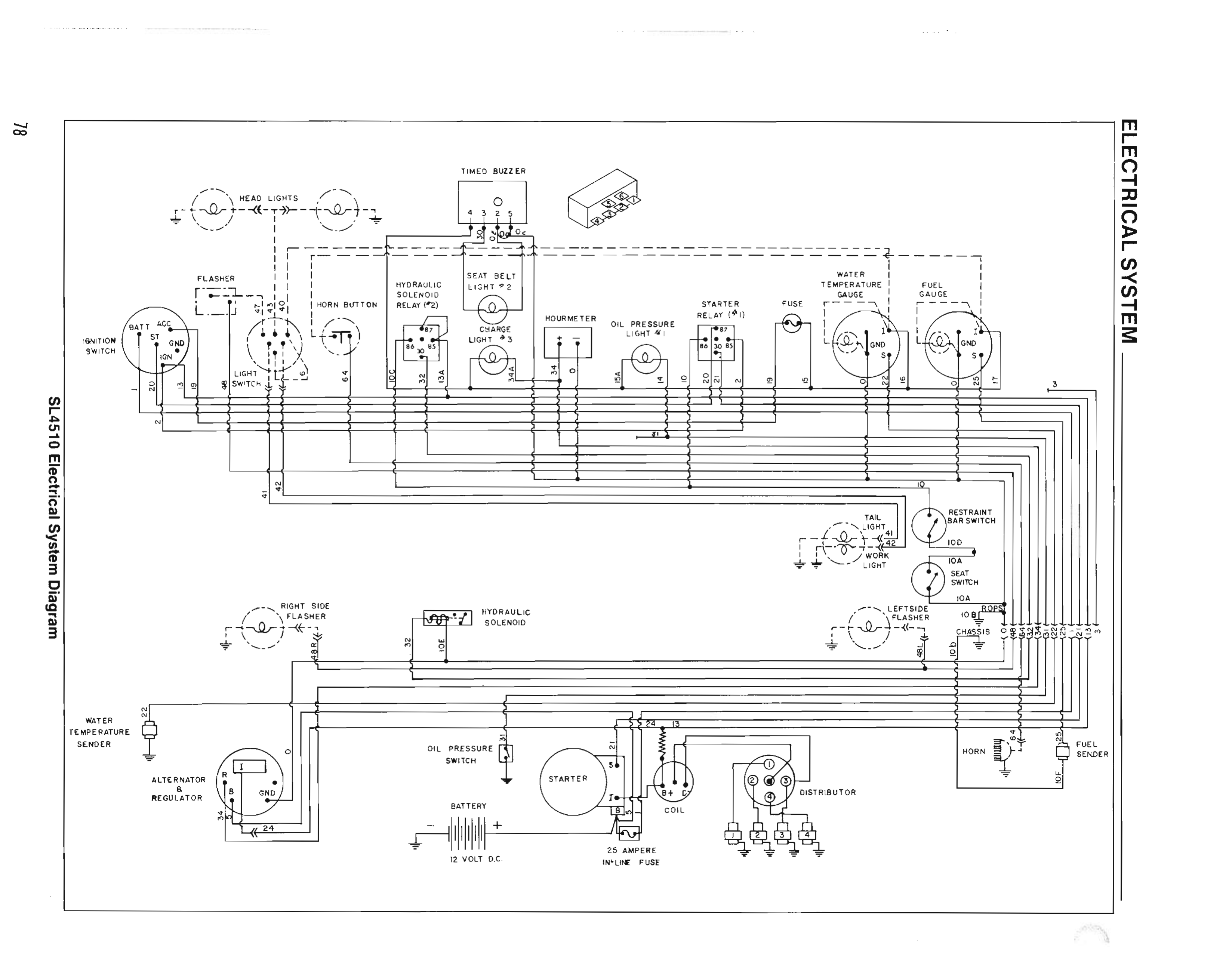
Traced from service manual 903931 p.78 (SL4510 Electrical System Diagram) with per-element provenance. 12 V DC · wet cell battery · 12 V starter · 37 A alternator (903931 p.3).
The interactive diagram below mirrors the manual page's component layout; its connecting lines
are logical links, not wire routes — the scanned diagram further down shows the
real runs. The 3D harness view is the one place routes are
drawn, and it draws them to two different standards on purpose: a tube is solid only where the
bend is visible on p.78, and broken where the placement is inferred. The three harness corridors
and the bulkhead riser's printed conductor order are traced; which of the ~15 parallel wires in a
band a given run occupies is not resolvable at 300 dpi, and the depth axis is a viewing device,
not machine geometry — nothing in the corpus says where this loom physically lies (903931 p.16 was
checked; it is chassis sheet metal and carries no harness).
Flow animation shows conventional-current direction and is illustrative only.
Dashed blue elements are INFERRED (read from
adjacency, not printed labels) and carry their reason; everything else cites the exact scan region
it was traced from — click any component to see its citation crop. Verification gates:
overlay check + part-number audit, receipts in
receipts/sl4510-electrical-3d-2026-08-30/.
The optional narration (🔊 buttons and diagnosis-mode chimes) is a clone of Dane
Cooper's own voice — synthetic, consent-bound and watermarked, never a live recording.
Its words are generated from this page's text and each shipped clip passed a transcript check
against its script. This page has no offline cache, so the voice needs a connection.
The schematic above connects components with straight chords. This view draws the same 41 connections along the routes the manual page actually lays out: down into the instrument-panel band, across to the bulkhead riser on the right edge, and along the engine-bay band. Runs sharing a corridor are pulled apart in depth so you can follow one by eye — drag to orbit, scroll to zoom. Colours are the circuit chips above; pick one to isolate it.
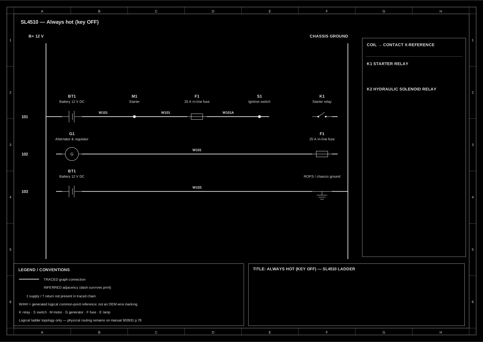
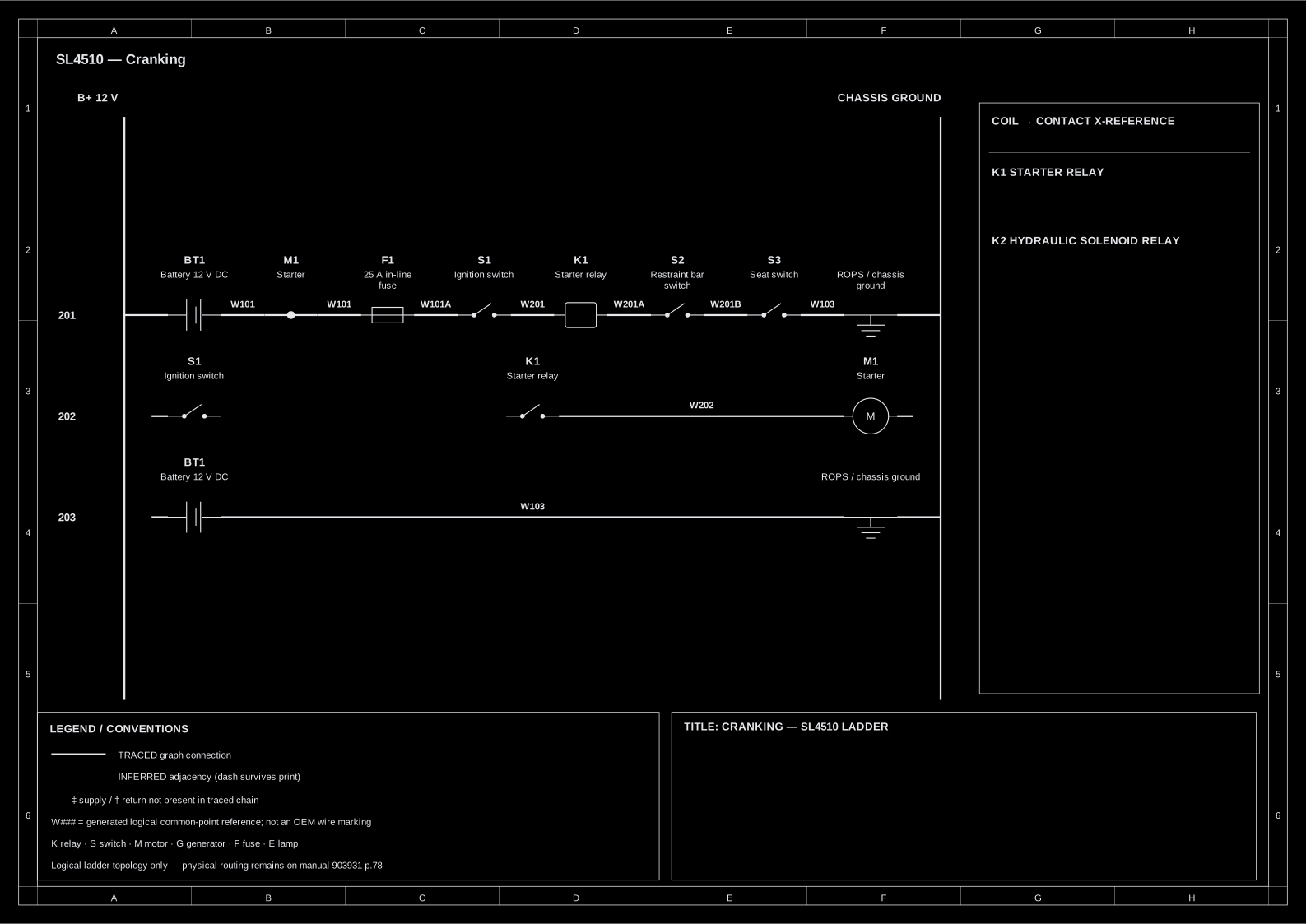
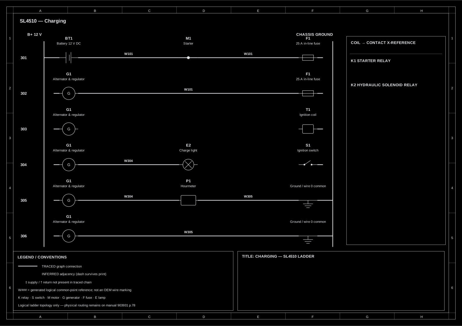
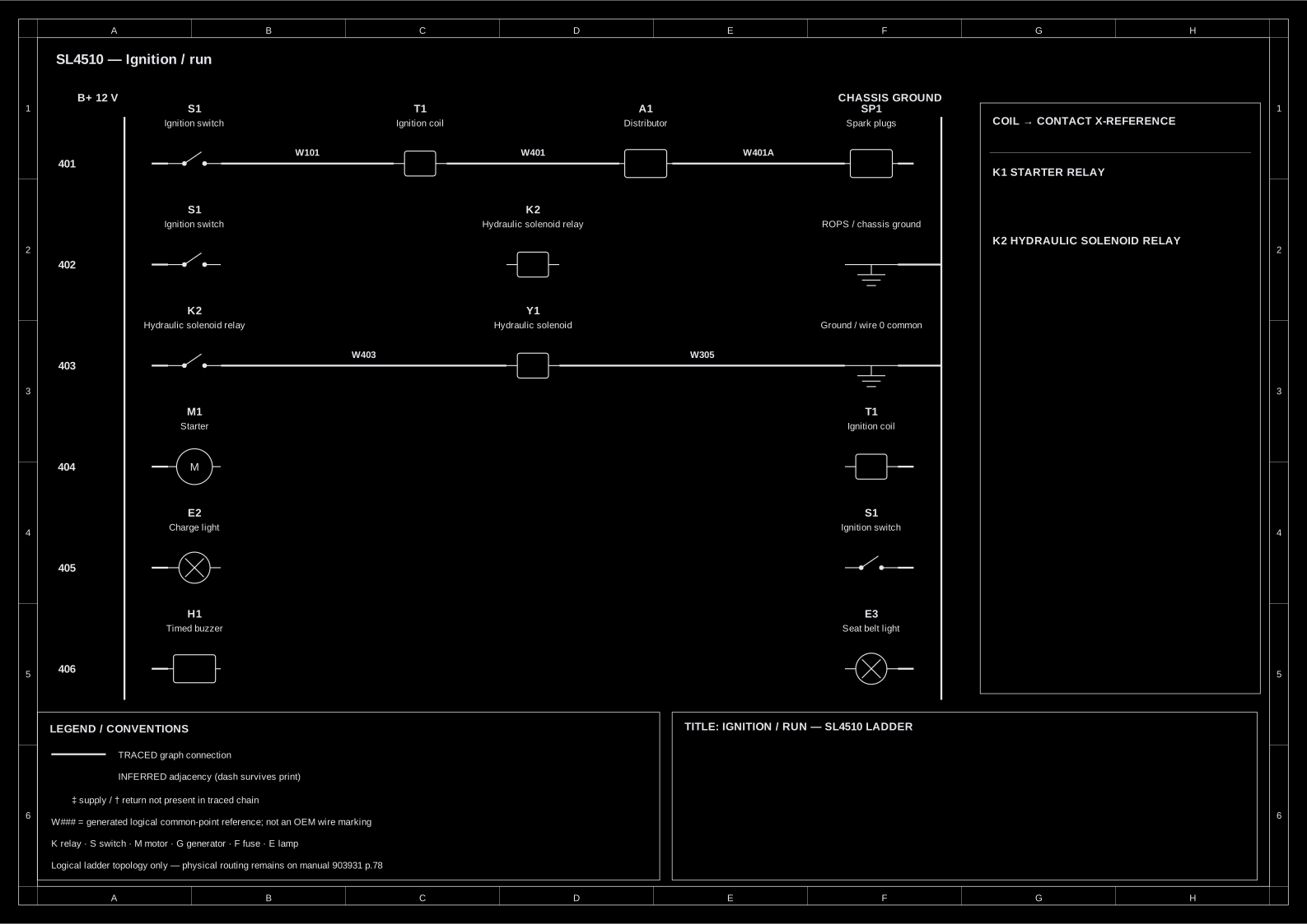
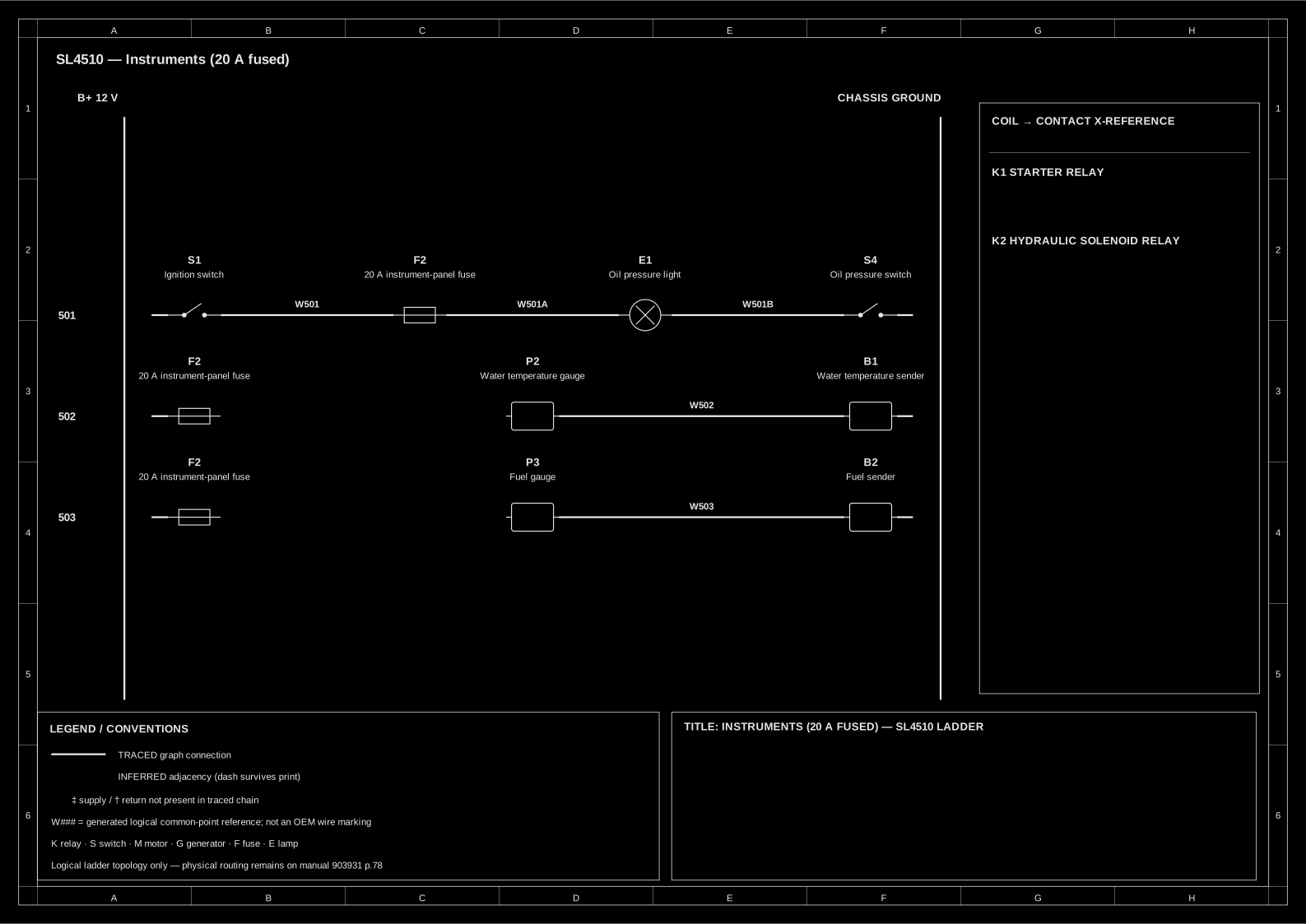
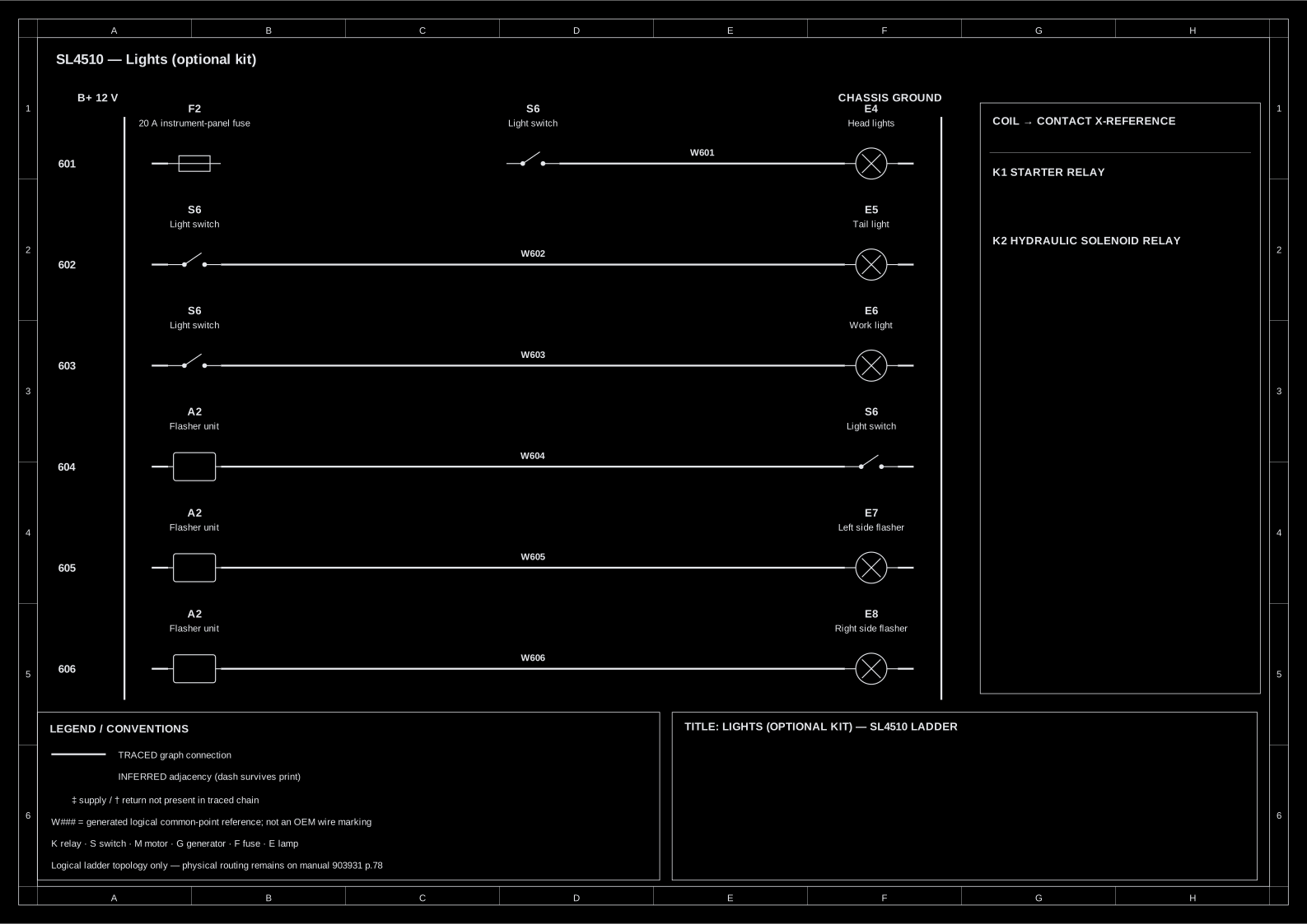
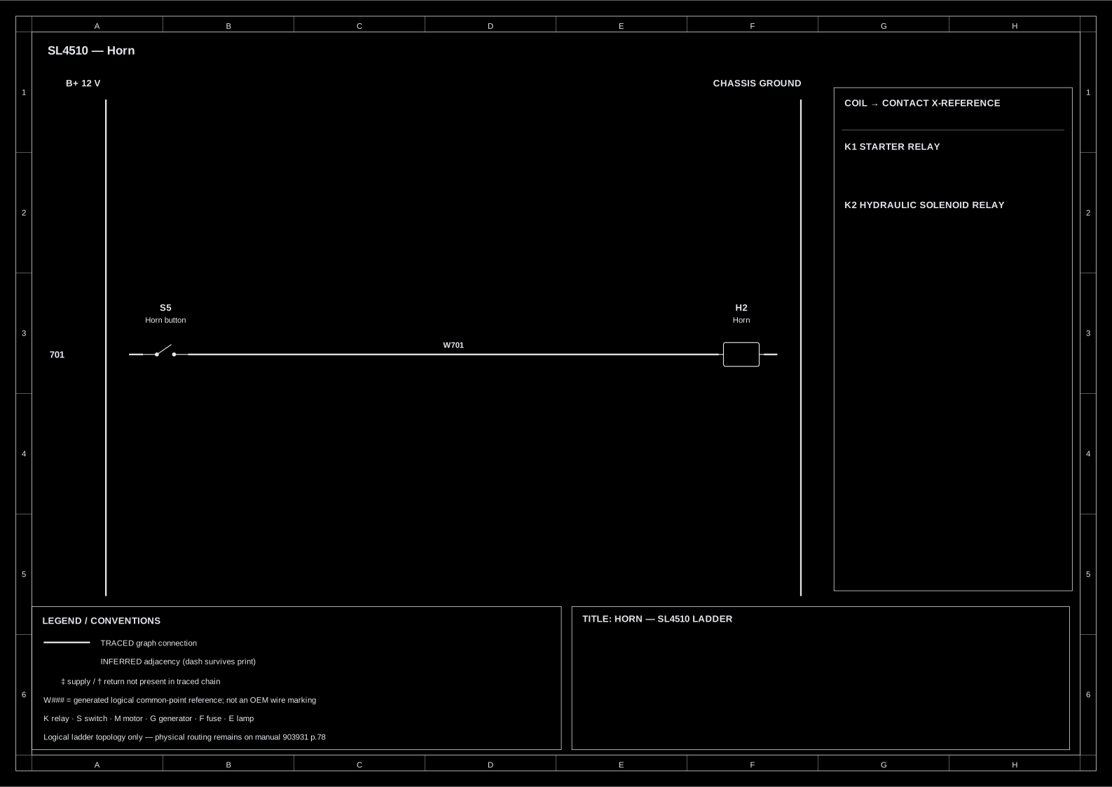
One IEC ladder sheet per circuit, generated from the same traced wiring graph
as the interactive diagram above (scripts/gen_ladder_diagrams.py — CI fails if
these drift from the graph). The SVGs use a dark screen theme and switch to white for printing.
Rails are logical — B+ left, chassis ground right; a rung only reaches the ground rail where
the traced flow does, and INFERRED connections stay blue-dashed, same as above. Wire colours
and gauges are omitted because every conductor label is illegible on the source scan — omitted,
never guessed.
The former 36-component monolith is now an index plus five subsystem sheets,
each with at most 12 graph components, followed by the seven focused circuit sheets. Hover or
click a conductor/component to isolate its circuit; the controls also provide native SVG
viewBox zoom/pan and one-sheet A3 printing. The original <img> remains as the
fallback. Supply is at the top and chassis grounds at the bottom: this is logical topology,
not the manual's physical wire route.
Generated by scripts/gen-schematic.mjs from
wiring-graph.json — the same traced graph as the interactive diagram and the
ladders. ELK is used sheet-by-sheet only where lint measures fewer crossings than the retained
graph-order BFS fallback. INFERRED is blue-dashed, optional lighting is long-dashed, and wire
colours/gauges remain omitted because the source scan does not make them legible.
| Fuse | Rating | Where | Protects | When it blows |
|---|---|---|---|---|
| Starter-circuit in-line | 25 A | at the starter B stud | everything — it is the master feed | entire electrical system dead (903931 p.76) |
| Instrument panel — part 071149 (holder 069745) | 20 A | instrument panel | gauges, panel switches, lights | gauges/lights dead, engine still runs |
Ratings CONFIRMED from 903931 p.76; part numbers from 904059 p.17. The alternator charge lead is unfused — remember that in the drain hunt.
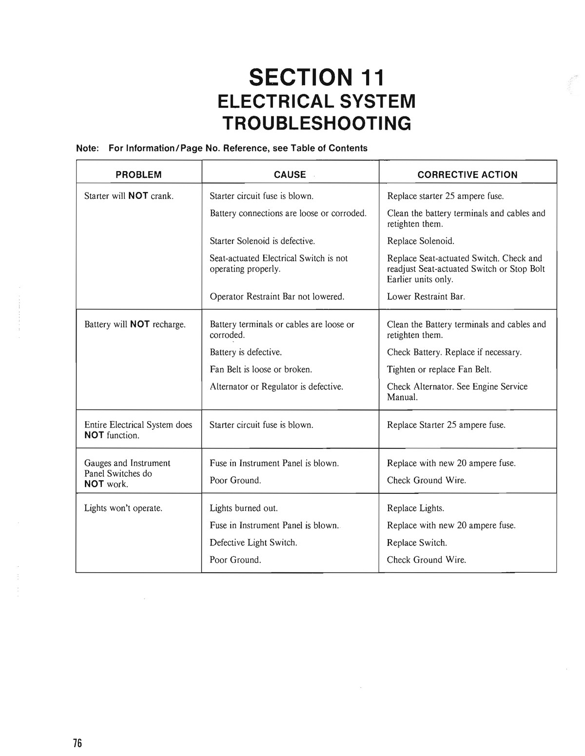
| Problem | Cause | Corrective action |
|---|---|---|
| Starter will NOT crank. | Starter circuit fuse is blown. | Replace starter 25 ampere fuse. |
| Battery connections are loose or corroded. | Clean the battery terminals and cables and retighten them. | |
| Starter Solenoid is defective. | Replace Solenoid. | |
| Seat-actuated Electrical Switch is not operating properly. | Replace Seat-actuated Switch. Check and readjust Seat-actuated Switch or Stop Bolt. Earlier units only. | |
| Operator Restraint Bar not lowered. | Lower Restraint Bar. | |
| Battery will NOT recharge. | Battery terminals or cables are loose or corroded. | Clean the Battery terminals and cables and retighten them. |
| Battery is defective. | Check Battery. Replace if necessary. | |
| Fan Belt is loose or broken. | Tighten or replace Fan Belt. | |
| Alternator or Regulator is defective. | Check Alternator. See Engine Service Manual. | |
| Entire Electrical System does NOT function. | Starter circuit fuse is blown. | Replace Starter 25 ampere fuse. |
| Gauges and Instrument Panel Switches do NOT work. | Fuse in Instrument Panel is blown. | Replace with new 20 ampere fuse. |
| Poor Ground. | Check Ground Wire. | |
| Lights won't operate. | Lights burned out. | Replace Lights. |
| Fuse in Instrument Panel is blown. | Replace with new 20 ampere fuse. | |
| Defective Light Switch. | Replace Switch. | |
| Poor Ground. | Check Ground Wire. |
The "Engine Service Manual" it refers to is the Ford 67/98 CID Industrial manual (KSG411/KSG416) — link in doc 09 §G.
Written for the Commercial Electric MS8301B. Three absolute rules: never in series with the starter or charging circuit (10 A fuse dies instantly — high-current paths get voltage-drop tests); never open/reconnect the circuit with a load on while the meter is in series; and move the red lead back to the VΩ jack before ANY voltage measurement — probing a battery with the lead still in a current jack is a dead short through the meter. It auto-sleeps after 30 min — press FUNC. Log every reading in the logbook.
Remove rings/watch; sparks near battery gas are the hazard, not shock. Keep the restraint bar up and stay off the seat — the interlocks hold the crank circuit open.
Free check 1: was the key left ON? Points ignition passes ~4 A key-on
(points usually stop closed) — that alone kills a battery overnight and burns the points.
Free check 2: clean/tighten both battery terminals and the cable ends (ground
063077, starter 075029); wash the dirt film off the battery top — it is a discharge path.
After charging: work lights on ~30 s (if fitted) or rest 2+ hours. A just-charged battery reads high and corrupts the baseline.
| Reading | State | Branch |
|---|---|---|
| ~12.6 V+ | full | go to Step 3 |
| ~12.4 V | ~75% | go on; note it |
| ≤12.0 V | discharged | charge fully first — draw tests on a flat battery mislead |
Record the number — Step 6's charging spec is relative to it.
Key OFF, seat empty, bar up, lights off. Lift the negative cable; red lead in the 10 A jack, DC A; meter bridges post ↔ cable clamp. A minus sign just means lead orientation — read the magnitude.
| Reading | Meaning | Branch |
|---|---|---|
| 0.00 on the 10 A jack | not yet proof — 0.01 A resolution hides tens of mA | confirm on the mA jack; only a mA-jack ~0 is a real zero → Step 6: the battery is dying of never-recharging, not theft |
| tens–hundreds mA | real drain | mA jack only below ~200 mA → Step 4 |
| ≥1 A | gross drain — the dead-overnight class | → Step 4; mind the meter's 2-min limit above 2 A |
| meter fuse blows at connect | drain is over 10 A — dead-short class | that IS the finding: skip series testing → Step 4 fuse pulls + Step 5 disconnect; inspect cables for chafe-through |
The 25–50 mA "normal" allowance belongs to computerized vehicles — applying it here masks the fault. Overnight self-discharge is ~0.2–0.5% — never the explanation.
Battery negative still off. Lift the meter off the negative post before wrenching — while it bridges, a wrench-to-chassis touch at the B stud blows its 10 A fuse silently, and a dead meter reads 0 A (which the table below would misread as "draw gone"). Remove the nut on the alternator B terminal, lift and tape the lug. Re-rig the Step-3 series meter, confirm it still shows the Step-3/4 drain (or beeps on continuity), then read.
| Result | Meaning | Action |
|---|---|---|
| draw gone | shorted rectifier diode or field/regulator stuck energized (~3 A class; intact diodes leak only µA). Factory-class line (CLAIMED, Prestolite family): >60 mA through the disconnected B lead = alternator leak — and this model has no isolation diode, so the rectifier sits directly across the battery | alternator 075863 = Prestolite 8AR2169F (aftermarket Leece-Neville 110-629) / regulator 075864 = OE 9RC2066 — a 4-screw plug-in module, a driveway job; belt 069152 while in there. Never pull the output lead with the engine running |
| draw unchanged | alternator innocent | inspect cables 075029/054985 for chafe-through; re-test the ignition switch by dropping its BATT feed |
Reconnect everything (25 A fuse back in) and move the red lead back to the VΩ jack first — Rule 3. The baseline must be a FULL battery's rest voltage (~12.6 V) — judged against a half-charged 12.4 V rest, a healthy 14.4 V system false-alarms as "overvoltage"; recharge and re-baseline if Step 2 read below ~12.5 V. Seat occupied + bar down = the machine is live: controls neutral, area clear, away from fan/belt. Engine running, DCV at the posts. Ford's factory spec is relative (CONFIRMED — factory pages 4-02/4-03; the full-charge baseline above is the factory's own precondition): at ~1500 rpm no-load the reading must be +1.0 to +2.0 V above your Step-2 resting voltage; at ~2000 rpm all loads on, at least +0.5 V above; more than +2.0 V above = regulator overvoltage. No rise → belt 069152 (adjust per 903931 p.91), excitation (this unit is ignition-excited — check the charge-light circuit 072345), a bad cable/connection, or the alternator/regulator. Before buying an alternator, run Step 7 on the charge path: fast idle with loads on, alternator B stud → battery + and battery − → block; over ~0.5 V total = cable/connection fault, not alternator (the factory table's own first cause). Keep clear of the fan and belt whenever the engine runs — probes go on with everything stopped. Ripple hint: AC V 4 V range across the battery — near ~0.5 VAC suggests a bad diode, but this meter is average-responding/40–400 Hz, so it corroborates Step 5, never replaces it. Charge light: ON with key/engine off is correct, OFF when running; stays on = not charging; never lights = bulb/feed — and a dead charge-light circuit can mean a never-exciting alternator. Do not full-field this alternator: the Ford book's A-to-F jumper test belongs to Ford's external-regulator layout; 075863 carries its regulator on the unit, and full-fielding an integral-regulator alternator risks unregulated output (factory p.4-04, architecture fence).
Disable the ignition first so the engine spins but cannot fire — lift the coil-to-distributor high-tension lead and clip it to the block (or disconnect wire 13 at the ballast resistor). With live ignition a healthy engine just STARTS, with your hands beside a spinning fan. Attach probes with everything stopped; crank in ~15 s bursts with rest between; reconnect the lead afterwards.
| Probe points (while a helper cranks) | Fault threshold |
|---|---|
| battery − post → engine block | >~0.2 V: clean/retighten ground cable 063077 |
| battery + post → starter B stud | >~0.2 V: clean/replace starter cable 075029 |
| starter B stud → starter case | reads the voltage at the starter (not a drop): should stay above ~9.5 V cranking; lower = sum the two drop rows + battery (R&R 903931 p.86) |
Night 1: full charge, log Step-2 voltage, negative cable OFF overnight. Night 2: cable ON, everything off. Cable-off up + cable-on dead → machine drain confirmed (Steps 3–5 find it). Cable-off ALSO down → the battery or its dirty case top, "new" or not. Both fine → intermittent, or short-run usage never recharging (Step 6 numbers decide).
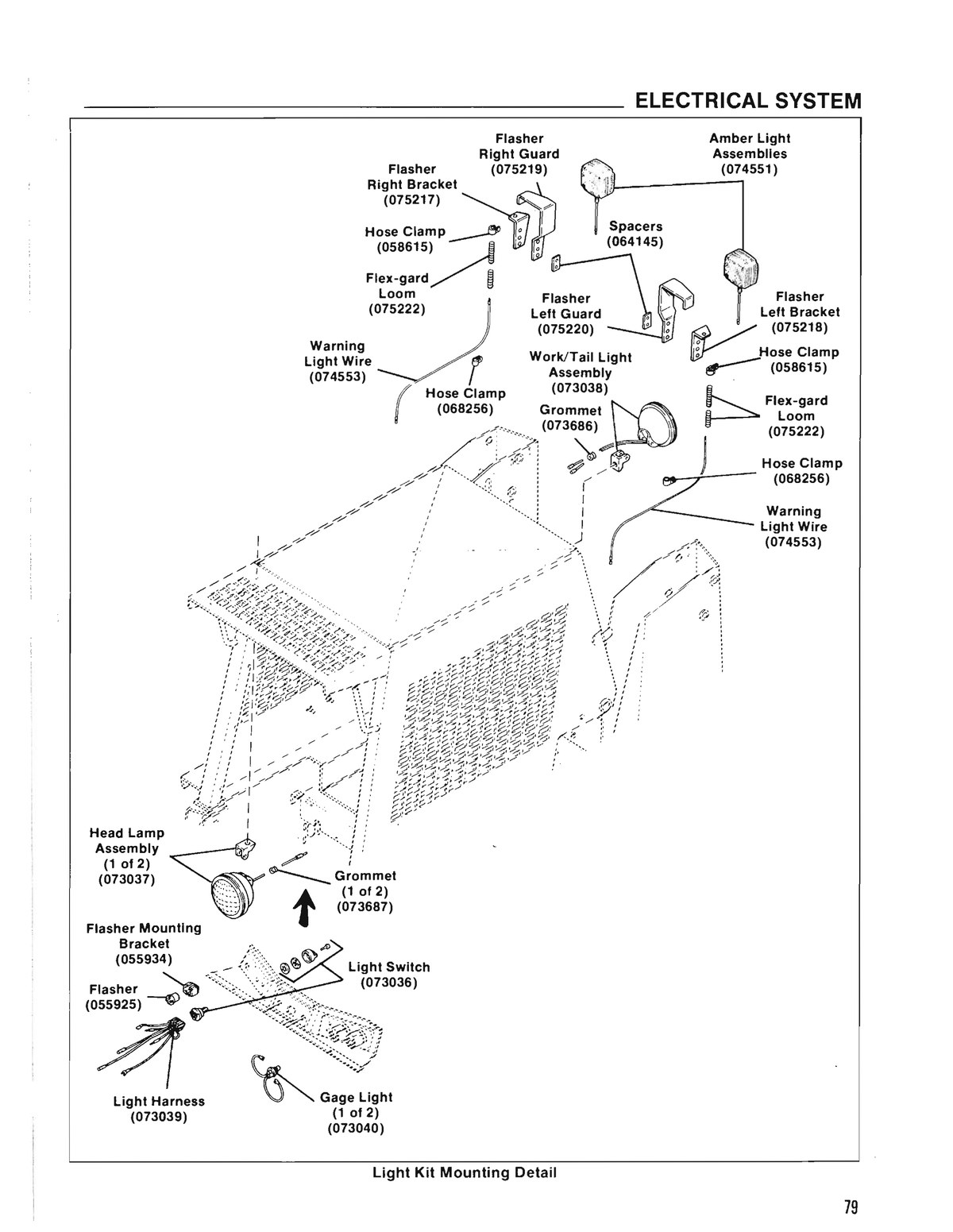
Five of the seven components this diagram declares now have 3D meshes, generated from the 600 dpi parts-manual line art. Orbit them. They are reconstructions, not scans — useful for recognising a part in your hand, not for taking dimensions off. The fifth — the 20 A panel fuse — came out of the 2026-09-01 free ZeroGPU window. A later holder candidate passed the machine gates but was withdrawn after the operator rejected its identity at G3.
All five came from Hunyuan3D-2.1, and that was not the incumbent choice. The two-lane comparison below covers the first four; the fifth, added 2026-09-01, ran on Hunyuan only (see the addenda under provenance). Every artifact either lane produced across those four parts has been scored — 56 meshes, one gate, no cherry-picking:
| part | Hunyuan3D-2.1 | TRELLIS.2 |
|---|---|---|
| alternator | 7/7 pass · 0.9194 | 7/7 pass · 0.5043–0.5045 |
| battery | 7/7 pass · 0.6722 | no mesh at all — 8 calls, 8 hard errors |
| starter relay | 7/7 pass · 0.5661 | 0/7 — flat billboard, 0.0111 |
| ignition switch | 11/11 pass · 0.1869 | 0/10 — flat slab, 0.032 |
| total | 32/32 pass | 7/24 pass (32 calls, 8 produced nothing) |
TRELLIS.2 is not simply worse — it is unpredictable. It matched Hunyuan on the alternator seven times out of seven, then returned a flat slab on two other parts and nothing at all on a third, while spending ~3.8× the triangles doing it. A lane that works perfectly on one part and silently returns a billboard on the next cannot be trusted without scoring every output, which is exactly why the gate exists. Measured, published either way: provenance below.
G2 min/max 0.9194 · PASS
G2 min/max 0.6722 · PASS
G2 min/max 0.1869 · PASS, but
marginally — the gate is 0.15. Extents 1.98 / 0.48 / 0.37: an
elongated barrel, which is the right shape for a switch, so the low ratio may be the part
rather than a bad reconstruction. Treat it as the least-certain of the five.
Re-run 11 times to test exactly that. Every run returned 29,976 triangles and
0.1869 — stdev 0.00 on both. The marginal score is a property of the part, not a
wobble in the pipeline: it lands on the same number every time. This mesh and the 20 A fuse below are the two
of the five with that evidence behind them.
G2 min/max 0.5661 · PASS
G2 min/max 0.2247 · PASS
(extents 1.99 / 1.98 / 0.45). Hunyuan3D-2.1 on ZeroGPU (tencent/Hunyuan3D-2.1
@ 61d23d8c, seed 1234 pinned), 2026-09-01 free window, replicate
fuse-20a-fuse-hunyuan-r1 — 3/3 replicates passed, the score
identical to every digit across its three replicates: geometrically stable, not bit-reproducible
(3 distinct sha256 for 3 runs; this file is
210f47d2…, 3,628,360 bytes). Source: 904059 p.17 ref 7, a
63×55 px, 14× upscale crop of the 600 dpi plate with the callout digits whitened. Its holder
(ref 8, 069745) was reconstructed separately: seed 1234 failed G2, and seed 99991 passed the
machine gates but failed operator G3: No — not a fuse holder. That candidate is
withdrawn; only the fuse model remains. G3 for the fuse itself remains the operator's call.
How these were made, and what is NOT claimed. 63 metered GPU calls, $13.89 of credit, both lanes — before the free-window addendum below, which brings it to 72 calls at the same $13.89. Geometry is stable at a fixed seed (min/max stdev 0.00000–0.00007) — but the files are not bit-reproducible: 21 runs of the ignition switch produced 21 distinct sha256 — and the 11 Hunyuan runs among them were geometrically identical to every digit measured. Same mesh, 11 different files. A mesh here cannot be verified by comparing file hashes; it can be verified by re-running and comparing geometry, which is a weaker guarantee than a checksum and worth saying plainly rather than glossing as "reproducible".
Free-window addendum, 2026-09-01. 9 further Hunyuan calls after the
provider-side ZeroGPU reset, every one completed in the guard's ledger; 1010 s of the
2,400 s free allowance by the guard's own count and 0 s of credit ($0.00). One lane
only, by evidence, not preference. The replicate meshes and their scores are archived privately as the
dataset kaaterskillsawmill/sl4510-wiring-meshes.
Paid seed-sweep addendum, 2026-09-02. One Hunyuan3D-2.1 shape-only
job tested seed and octree-resolution sensitivity. HF Job
6a97dd150718b0f6d89101ef ran on l4x1 for 38 billed minutes ($0.51). The
seed-99991, resolution-256 candidate passed G2 at 0.210751, then failed operator G3: No — not a
fuse holder. The candidate is withdrawn and its mesh is not served.
G3 remains unadjudicated for the five meshes shown above. The withdrawn holder candidate has the final operator verdict recorded above.
Why two of the seven still have no mesh — measured now, not predicted. An earlier version of this paragraph predicted that refs 6/7/8 had no single-object crop and that ref 25 would fail the gate as a flat plate. On 2026-09-01 all three crops were cut and put to the gate in the free ZeroGPU window, three replicates each, Hunyuan3D-2.1 only — every TRELLIS.2 call on line art that day had ended in a Space-side AppError while keeping its full reservation. The holder is part of the fuse's catalogue key, not a seventh component. A paid 2026-09-02 sweep later changed the seed and resolution and produced a machine-pass candidate that the operator rejected at G3:
| part | crop (600 dpi) | G2 result | verdict |
|---|---|---|---|
| 20 A fuse 071149 (ref 7) | 63×55 px, 14× upscale | 0.2247 | PASS — shipped above |
| fuse holder 069745 (ref 8) | fuse-20a-ref8-holder.png | 0.0753 (2026-09-01, seed 1234); 0.210751 (2026-09-02, seed 99991) | WITHDRAWN — operator G3: No |
| seat switch 076057 (ref 25) | 188×120 px, 4.7× upscale | 0.1331 | FAIL — flat plate (extents 1.99 / 0.41 / 0.26); the prediction held |
| 25 A in-line fuse | not illustrated anywhere in 904059 — nothing to crop; no spend closes this one | ||
The fuse prediction was wrong: single-object crops could be cut, and the fuse reconstructed at 0.2247. The one flatness prediction — ref 25 — was right. The holder was never predicted flat: it was predicted uncroppable, then proved croppable but flat at seed 1234. Seed 99991 passed the geometry gate, but the operator said it was not a fuse holder, so it was withdrawn. The page now carries both the machine measurements and the final human verdict. Fixed-seed repeats remain geometrically stable; seed choice can change G2, but it cannot establish identity. Flat parts remain a scanner job: an orthographic outline at 600 dpi beats a mesh for anything you would put on a laser cutter.